Refrigerating Apparatus

a technology of refrigerating apparatus and compressor, which is applied in the field of refrigerating apparatus, can solve the problems of high ability and difficulty in operating with the optimum amount of circulated refrigerant, and achieve the effect of ensuring the reliability of the compressor, preventing excessive superheat operation and wet operation, and maximum ability

Inactive Publication Date: 2009-01-27
DAIKIN IND LTD
View PDF20 Cites 8 Cited by
  • Summary
  • Abstract
  • Description
  • Claims
  • Application Information

AI Technical Summary

Benefits of technology

[0037]According to the aforementioned first refrigerating apparatus, the controller brings the receiver temperature close to the target receiver temperature, whereby the refrigerant amount stored in the receiver can be made to the amount corresponding to, for example, the season, whereby the amount of the circulated refrigerant can be made to the proper amount. Consequently, it is possible to operate the apparatus with the optimum amount of the circulated refrigerant through the year, whereby an excessive superheat operation and a wet operation can be prevented. This secures the reliability of the compressor. Further, by controlling the amount of the circulated refrigerant, a system such as heat pump type hot-water supply equipment having this refrigerating apparatus can exhibit maximum ability.
[0038]According to the aforementioned second refrigerating apparatus, the controller brings the receiver temperature close to the target receiver temperature, whereby it is ensured that the amount of the circulated refrigerant is made to the expected amount (the amount of the circulated refrigerant corresponding to the season), and also a stable operation can be made. Further, if the target receiver temperature is calculated based on the outside air temperature, the amount of the circulated refrigerant can be easily controlled.
[0039]According to the aforementioned third refrigerating apparatus, the controller brings the receiver temperature close to the target receiver temperature, whereby it is ensured that the amount of the circulated refrigerant is made to the expected amount (the amount of the circulated refrigerant corresponding to the season), and also a stable operation can be made. Further, if the target receiver temperature is calculated based on the superheat degree, the amount of the circulated refrigerant can be controlled with high precision.
[0040]According to the aforementioned forth refrigerating apparatus, the controller brings the receiver temperature close to the target receiver temperature, whereby it is ensured that the amount of the circulated refrigerant is made to the expected amount (the amount of the circulated refrigerant corresponding to the season), and also a stable operation can be made. Further, if the target receiver temperature is calculated based on the outside air temperature and the superheat degree, the amount of the circulated refrigerant can be controlled with higher precision.
[0041]According to the aforementioned fifth refrigerating apparatus, the controller brings the receiver temperature close to the target receiver temperature by adjusting the opening of the adjusting valve, whereby the amount of the circulated refrigerant can be easily controlled. Further, since the control for bringing the receiver temperature close to the target receiver temperature is such a simple control as adjusting the opening of the adjusting valve, the controller can be simplified. This leads to a reduction in the cost of the refrigerating apparatus.
[0042]According to the aforementioned sixth refrigerating apparatus, it is ensured that the mount of the circulated refrigerant can be made to the expected amount, whereby an excessive superheat operation and a wet operation can be prevented. This secures the reliability of the compressor. Further, by controlling the amount of the circulated refrigerant, a system such as heat pump type hot-water supply equipment having this refrigerating apparatus can exhibit maximum ability. Moreover, if the opening of the adjusting valve is adjusted based on the outside air temperature, it is possible to simplify the computation for controlling the amount of the circulated refrigerant.

Problems solved by technology

Still, the alternative refrigerant such as R-134a has a problem of having a high ability to cause a greenhouse effect or the like.
Thus, it has been difficult to operate with the optimum amount of circulated refrigerant unless some measures are taken.

Method used


Image

  • Refrigerating Apparatus
  • Refrigerating Apparatus
  • Refrigerating Apparatus

Examples


Embodiment Construction

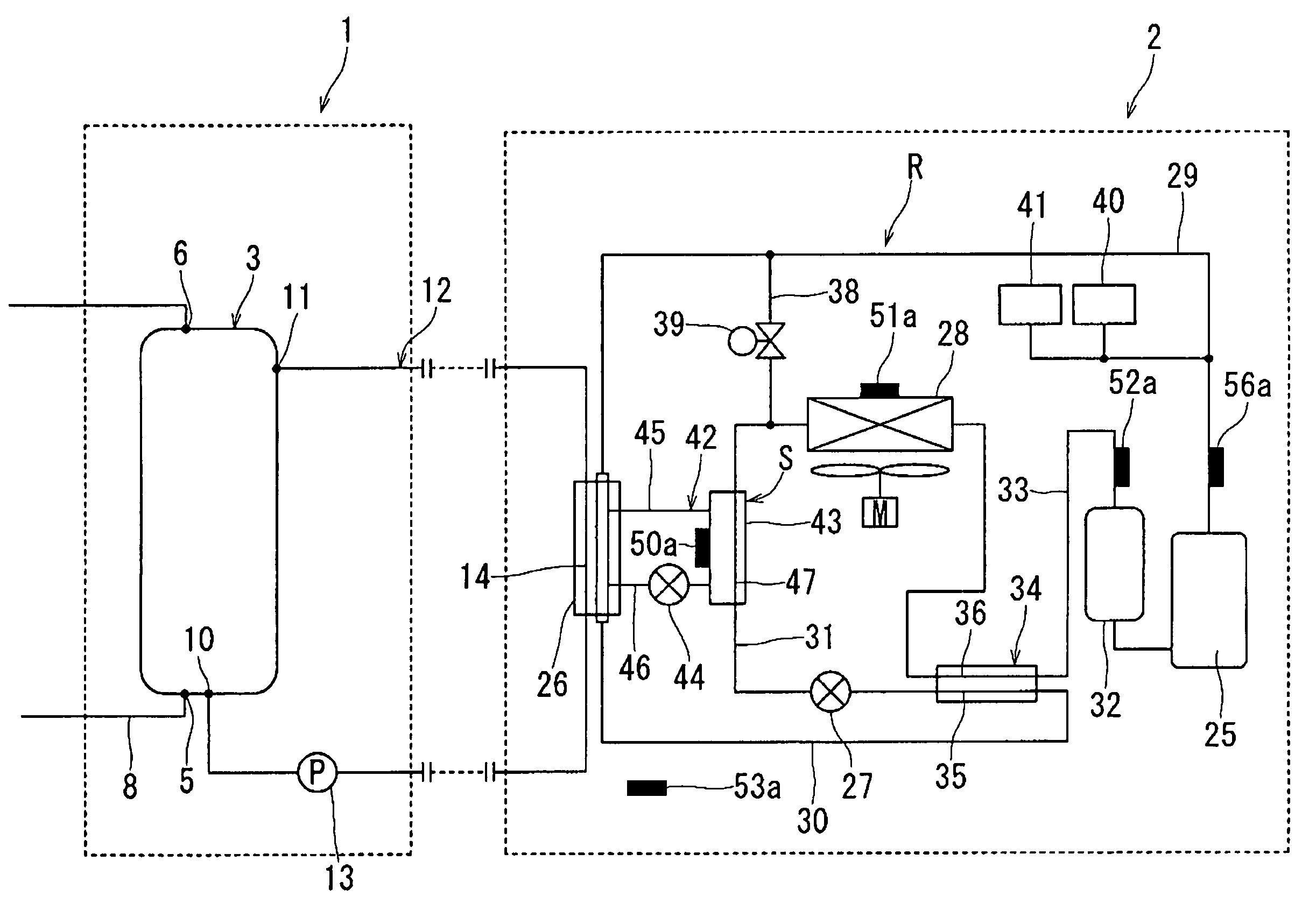
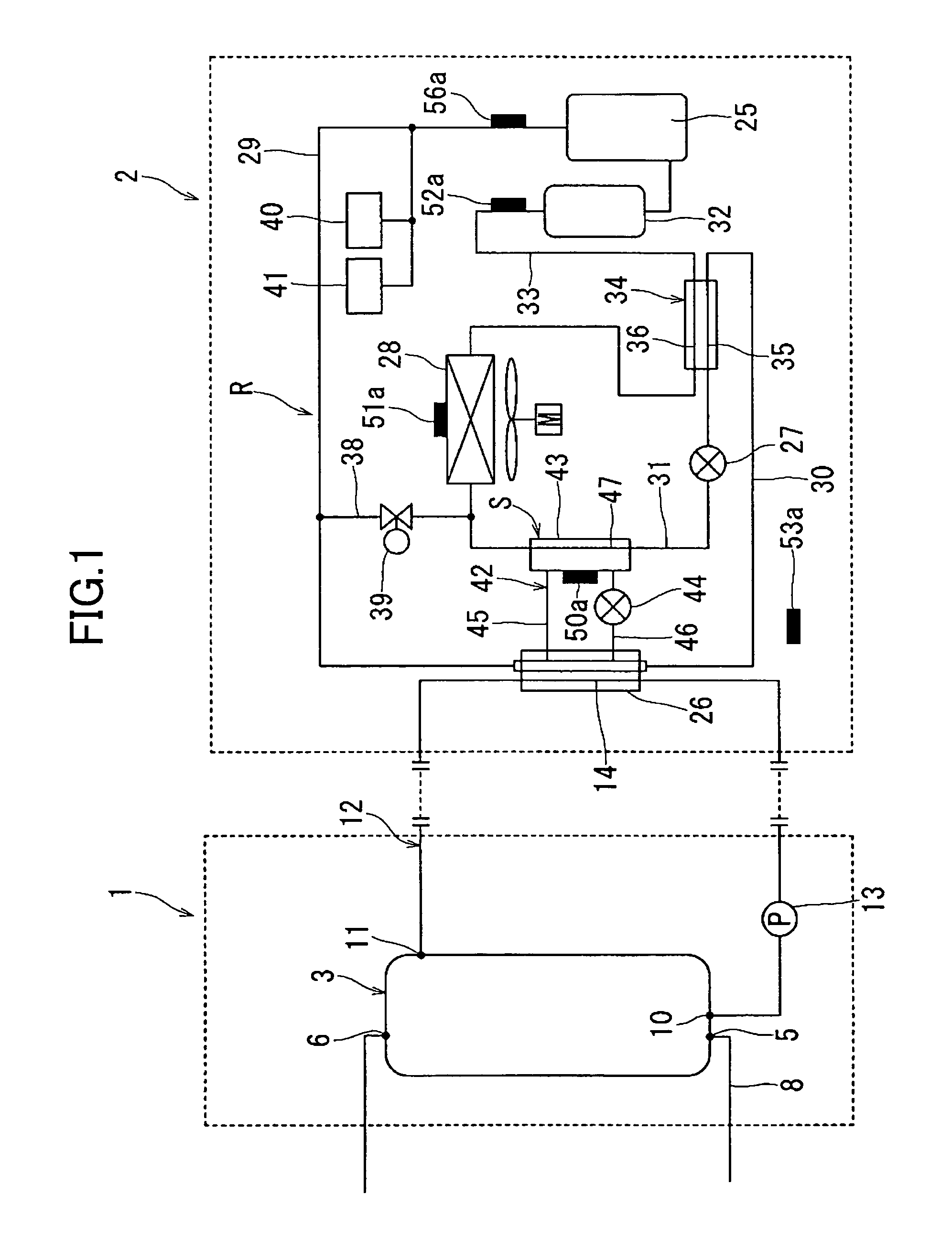
[0055]Next, a specific embodiment of a refrigerating apparatus according to the present invention will be explained in detail with reference to the drawings. FIG. 1 shows a schematic diagram of heat pump type hot-water supply equipment using a refrigerating apparatus according to the present invention. This heat pump type hot-water supply equipment is equipped with a tank unit 1 and a heat source unit 2, and heats water (hot water) of the tank unit 1 by the heat source unit 2.

[0056]The tank unit 1 includes a hot-water reservoir tank 3, and the hot water stored in the hot-water reservoir tank 3 is supplied to, for example, a bath tub (not shown). Thus, in the hot-water reservoir tank 3, there are provided a water supply opening 5 to the bottom wall thereof, and a tapping hole 6 to the upper wall thereof. Water is supplied from the water supply opening 5 to the hot-water reservoir tank 3, and hot water of high temperature is supplied from the tapping hole 6. Further, in the hot-water ...


PUM


Abstract

A refrigerant circuit R includes, a compressor 25 for compressing a refrigerant to a pressure higher than the critical pressure, a gas cooler 26, a motor-operated expansion valve 27, and an evaporator 28, and uses as a refrigerant a natural system refrigerant. A receiver 43 is provided to the high-pressure side of the refrigerant circuit R. There is provided an adjusting valve 44 for adjusting the refrigerant amount flowing through the inside of the receiver 43. A controller 55 adjusts the opening of the adjusting valve 44 so as to bring the temperature of the receiver 43 close to a target receiver temperature.

Description

TECHNICAL FIELD[0001]The present invention relates to a refrigerating apparatus having supercritical refrigerating cycles using as a refrigerant a natural system refrigerant, which apparatus is suitable to be used for, for example, a heat-source unit of heat pump type hot-water supply equipment.BACKGROUND ART[0002]Heat pump type hot-water supply equipment is equipped with, in general, a tank unit 71 having a hot-water reservoir tank 70, and a heat-source unit 73 having a refrigerant circuit 72, as shown in FIG. 7. The refrigerant circuit 72 is so configured as to connect a compressor 74, a hydrothermal exchanger 75, an expansion valve 77, and an evaporator 78 in order. The tank unit 71 includes the hot-water reservoir tank 70 and a circulation path 79. The circulation path 79 is provided with a pump 80 for water circulation and a heat exchange path 81 which constitutes a part of the hydrothermal exchanger 75.[0003]Here, the operation of the aforementioned heat pump type hot-water su...

Claims


Application Information

Patent Timeline
Patent Type & Authority Patents(United States)
IPC IPC(8): F25B41/04F25B39/04F25B1/00F25B9/00F25B30/02F25B40/00F25B45/00
CPCF25B9/008F25B40/00F25B45/00F25B30/02F25B2309/061F25B2339/047F25B2400/0403F25B2400/053F25B2400/16F25B2400/19F25B2600/2523F25B2700/2106F25B2700/2108F25B2700/21151F25B2700/21152
Inventor NAKAYAMA, HIROSHISAKAMOTO, SHINICHI
Owner DAIKIN IND LTD
Why Eureka
Try Eureka