System for supplying molten metal, container and a vehicle

a technology for supplying systems and molten metals, applied in the direction of rigid containers, transportation items, packaging, etc., to achieve the effect of low cos

Inactive Publication Date: 2009-01-27
HOEI SHOKAI CO LTD
View PDF12 Cites 49 Cited by
  • Summary
  • Abstract
  • Description
  • Claims
  • Application Information

AI Technical Summary

Benefits of technology

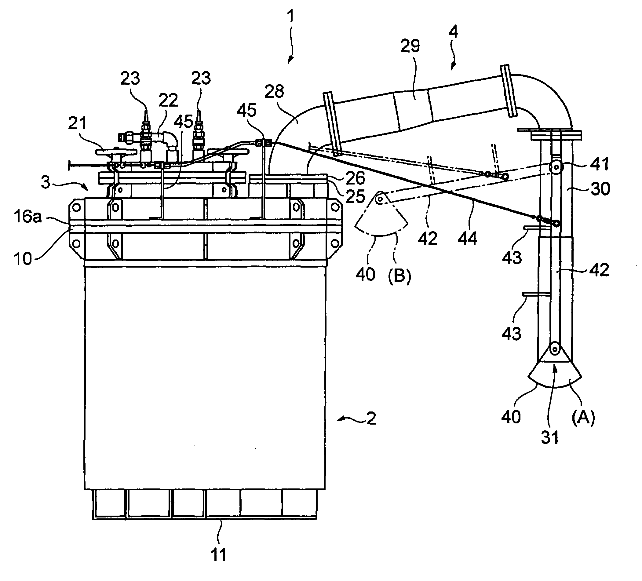
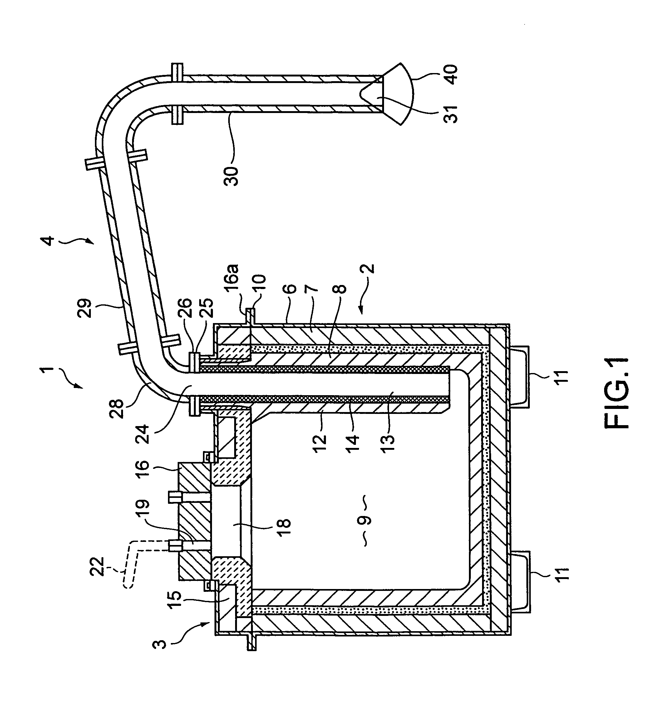
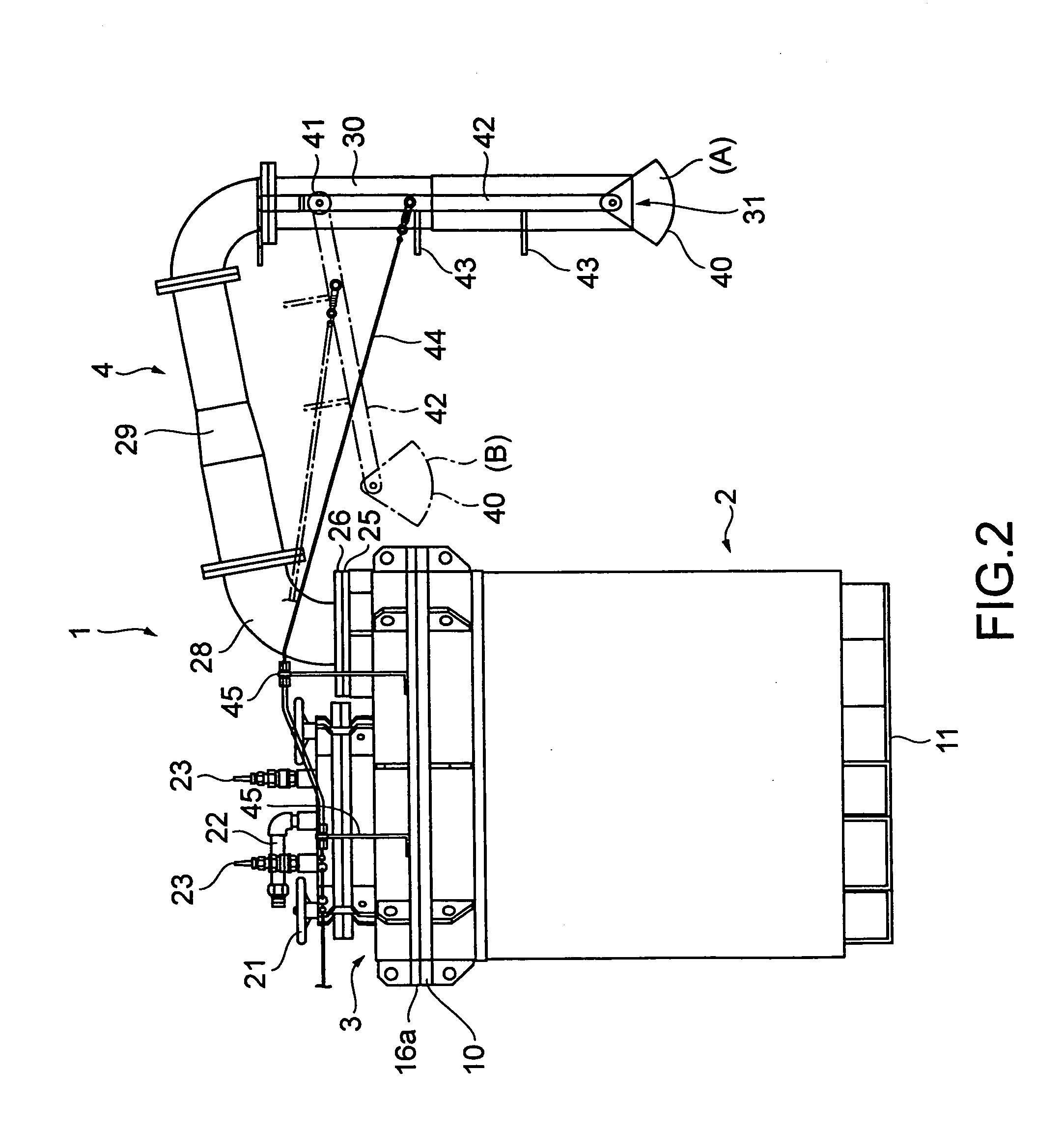
[0027]According to the present invention, since the reception dish can receive molten metal that flows from the outlet of the pipe, the molten metal that resides in the pipe immediately after the supply of the molten metal is stopped does not drip from the pipe. In addition, since the reception dish is rotated and moved by the wire pull and return mechanism mounted on the vehicle side through the wire, the reception dish can be rotated and moved at low cost. Moreover, since the wire pull and return mechanism lifts up and down as the container lifts up and down, the reception dish can be rotated and moved by such a simple structure through the wire.
[0028]In addition, according to the present invention, the reception dish that receives molten metal that drips from the outlet of the pipe can be securely moved to a proper place at proper timing without intervention of the operator.

Problems solved by technology

However, when such a compression type container is used, immediately after the supply of molten aluminum is stopped, the molten aluminum resides in the pipe.

Method used


Image

  • System for supplying molten metal, container and a vehicle
  • System for supplying molten metal, container and a vehicle
  • System for supplying molten metal, container and a vehicle

Examples


other embodiment 1

[0057]In the foregoing embodiment, the fulcrum 41 is disposed at the predetermined position of the holding members 42. However, as shown in FIG. 6, when the third member 30 of the pipe 4 extends downwardly with an angle, not straightly, a fulcrum member 61a is mounted to the pipe 4. The fulcrum member 61a may be adjusted so that the fulcrum 41 of the holding members 42 is placed just above the outlet 31. In this case, when the fulcrum 41 of the holding members 42 is horizontally movable on the fulcrum member 61a, the position of the fulcrum 41 of the holding members 42 and the position of the outlet 31 can be easily adjusted.

[0058]In the foregoing embodiment, the wire pull and return mechanism 59 is disposed at the column that extends in the third direction approximately opposite to the direction in which the pipe 4 of the carriage 52 extends. However, as shown in FIG. 7, the wire pull and return mechanism 59 may be disposed at a column that extends in the same direction as the pipe...

other embodiment 2

[0060]FIG. 8 is a sectional view showing the structure of a molten metal supplying container according to an embodiment of the present invention. FIG. 9 is a front view showing the structure of the molten metal supplying container shown in FIG. 8. FIG. 10 is a plan view showing the structure of the molten metal supplying container shown in FIG. 8.

[0061]A container for supplying molten metal (hereinafter referred to as the container) 101 has a container main body 102 and a pipe 104. The container main body 102 has a lid 103.

[0062]The container main body 102 has a frame body 106, a heat-insulating layer 107, and a refractory layer 108. The frame body 106 is made of metal and formed in a bottomed cylindrical shape. The heat-insulating layer 107 and the refractory layer 108 are made of elastic materials and are disposed on an inner wall of the frame body 106. A storage portion 109 is disposed inside the refractory layer 108. The storage portion 109 stores molten aluminum. A flange 110 i...

other embodiment 3

[0094]Next, another embodiment of the present invention will be described.

[0095]FIG. 14 is a schematic diagram showing the structure of peripheral sections of the three-way valve 160 according to another embodiment of the present invention. A breather 170 that is a flow restriction portion is disposed in front of the third valve opening 164, which leads to outer air, of the three-way valve 160.

[0096]The breather 170 is composed of a breather main body 171, a steel scrubber 172, and punched metal 173. The breather main body 171 contains the steel scrubber 172 as a restriction member. The punched metal 173 is a lid that closes the breather main body 171. Reference numeral 174 is a stop ring that secures the punched metal 173. The restriction member is selected or structured so that it has selectivity that allows for example air to pass and molten aluminum not to pass. When, for example, molten metal flows in the breather main body 171, it removes heat from the molten metal so as to in...


PUM

PropertyMeasurementUnit
angleaaaaaaaaaa
angleaaaaaaaaaa
pressureaaaaaaaaaa

Abstract

A molten metal supplying system comprising a container having a main body capable of being hermetically sealed and having a passage through which compressed gas is received, a pipe having an outlet supplying molten metal in the container to the outside, the outlet downwardly extending, a reception dish receiving the molten metal capable of being placed below the pipe outlet, a holding member having a fulcrum to the pipe rotatably holding the reception dish, a wire with a first and second end, the first end connected to the reception dish or holding member, a pair of channel members at the outer bottom of the container main body, and a vehicle having a fork that can be inserted and removed from the channel members, a carriage on which the fork is mounted, a lift mechanism for lifting up and down the carriage, and a wire pull and return mechanism mounted on the carriage pulling and returning the wire with it's second end.

Description

FIELD OF THE INVENTION[0001]The present invention relates to a molten metal supplying system, a container, and a vehicle used to supply for example molten aluminum.BACKGROUND OF THE INVENTION[0002]In a factory where aluminum is molded using many die-casting machines, an aluminum material is often supplied not only from within the factory but also from outside of the factory. In such a case, a container storing aluminum in a melt is carried from a factory on the material supply side to a factory on the molding side to supply to each of the die-casting machines the material kept in the melt.[0003]A conventional container that stores molten metal has a pot-shaped structure of which a supply pipe is disposed on a side wall. When a container is inclined, molten metal is supplied from the pipe to a die-cast side holding furnace.[0004]Japanese Utility Model Registration Laid-Open Publication No H3-31063 discloses a technology of which molten aluminum is supplied by a compression system.[00...

Claims


Application Information

Patent Timeline
Patent Type & Authority Patents(United States)
IPC IPC(8): B22D41/58
CPCB22D35/00B22D39/06B22D41/50B22D21/04B22D46/00F16B35/00
Inventor MIZUNO, HITOSHISAITOH, TOSHIOIMANAKA, TAKEO
Owner HOEI SHOKAI CO LTD
Why Eureka
Try Eureka