Probing pads in kerf area for wafer testing

a technology of kerf area and probe pad, which is applied in the field of wafer testing, can solve problems such as damage to bond pads

Inactive Publication Date: 2009-01-27
GLOBALFOUNDRIES INC
View PDF18 Cites 35 Cited by
  • Summary
  • Abstract
  • Description
  • Claims
  • Application Information

AI Technical Summary

Benefits of technology

[0009]The present invention provides a structure (and a method for forming the same) in which wafer testing is performed without damaging the bond pads.

Problems solved by technology

This results in the bond pads being damaged, which is undesirable for the assembly process.

Method used


Image

  • Probing pads in kerf area for wafer testing
  • Probing pads in kerf area for wafer testing
  • Probing pads in kerf area for wafer testing

Examples


Embodiment Construction

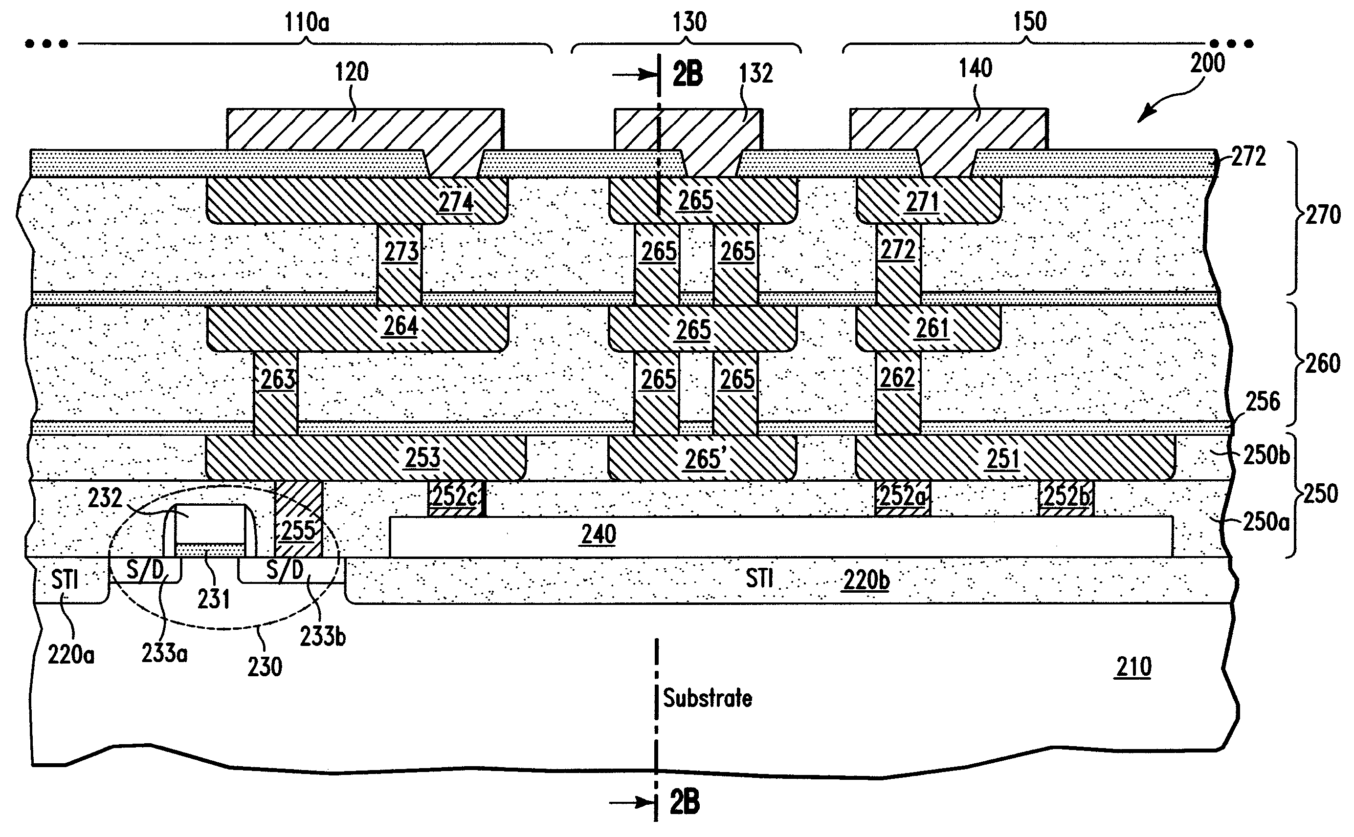
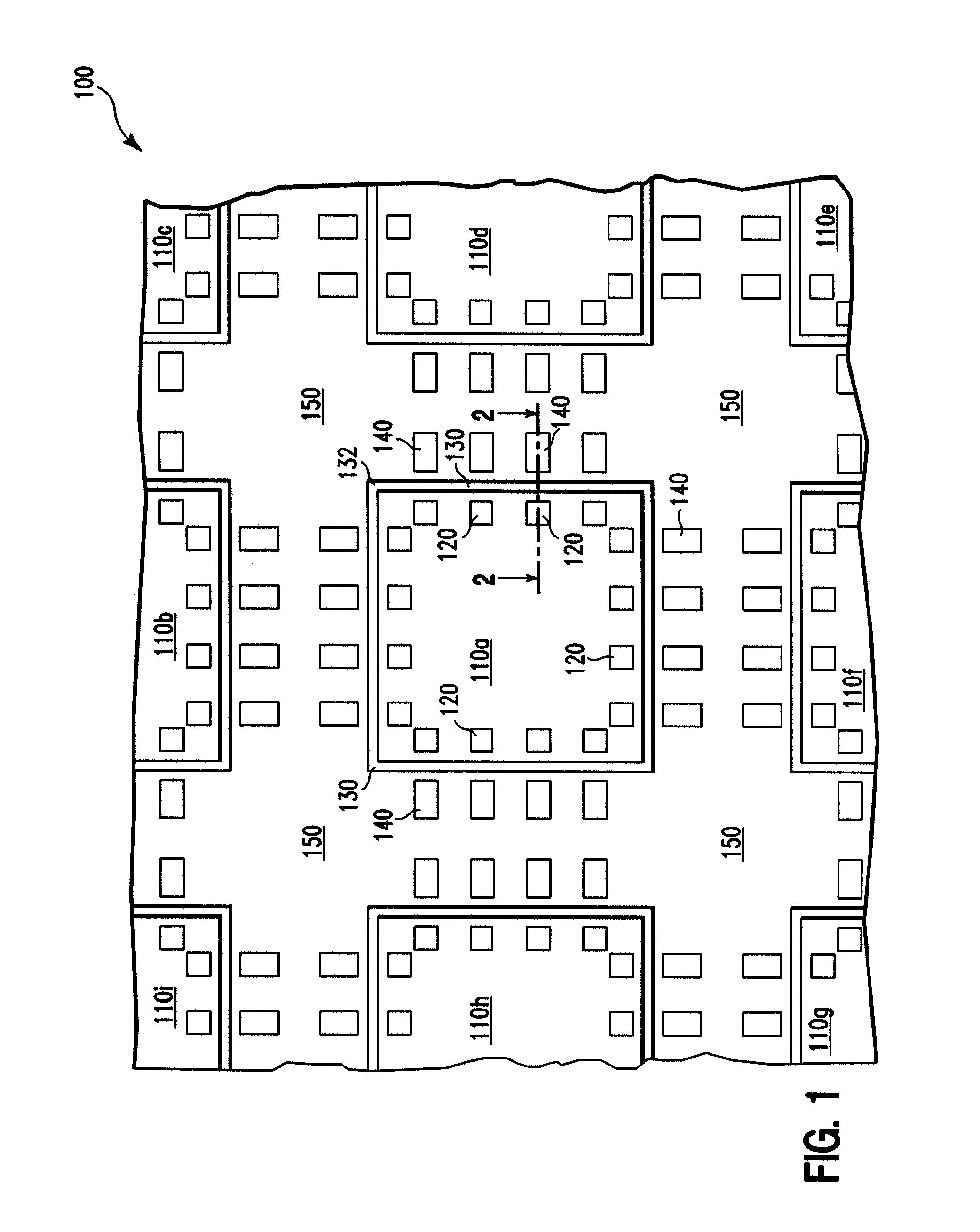
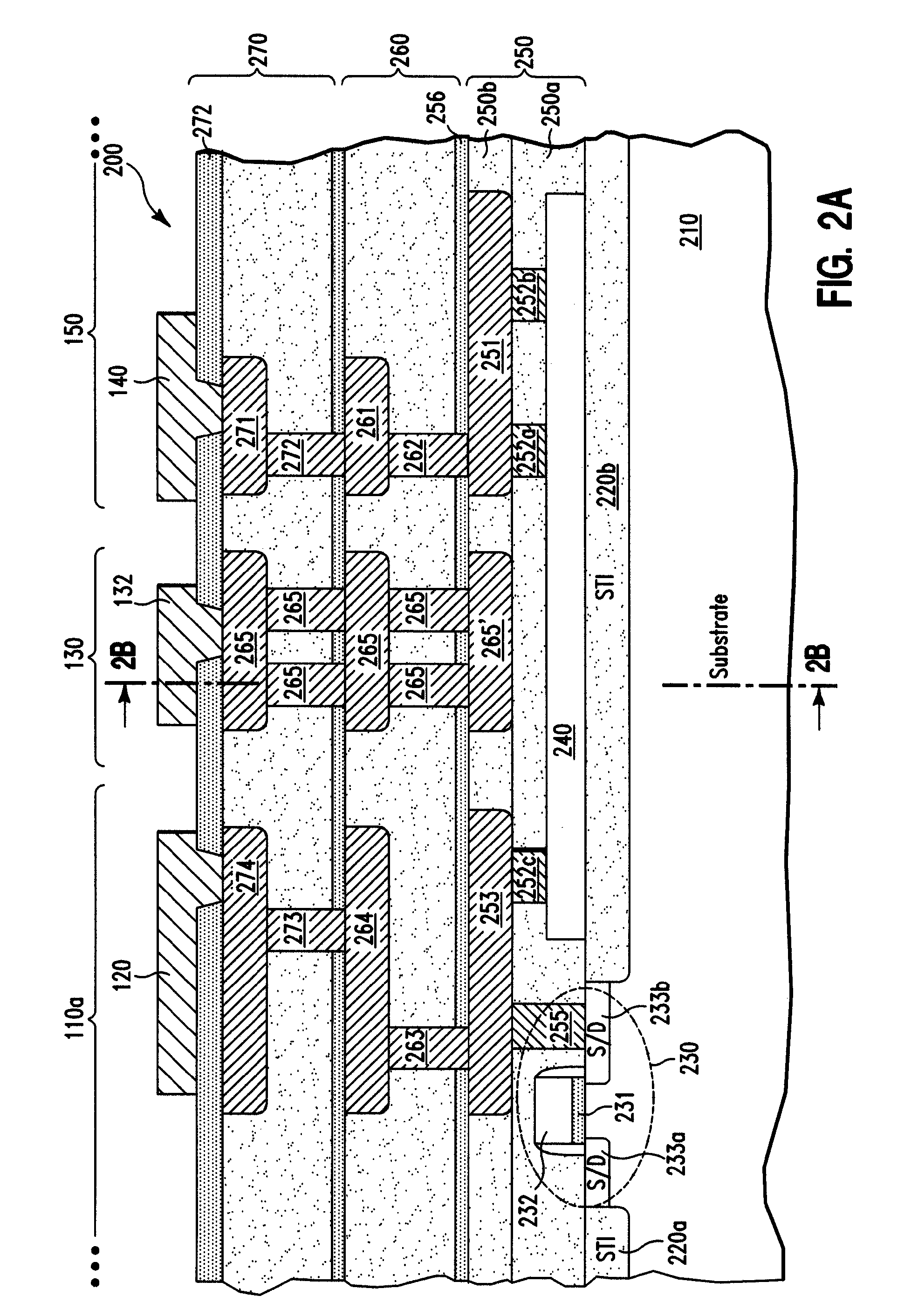
[0012]FIG. 1 illustrates a top down view of a wafer 100, in accordance with embodiments of the present invention. For illustration, the wafer 100 comprises 9 integrated circuits (i.e., chips) 110a-110i and other structures associated with the chips 110a-110i. In general, the wafer 100 can comprise N chips, N being a positive integer. Of the chips 110a-110i, only the chip 110a and its associated structures are fully described and fully shown in FIG. 1. The wafer 100 further comprises a kerf region 150 (i.e., dicing channels) physically separating the chips 110a-110i. During chip separation (i.e., chip dicing), in one embodiment, a blade (not shown) can be used to cut along the kerf region 150 so as to separate the chips 110a-110i from each other.

[0013]In one embodiment, the chip 110a comprises, illustratively, 16 bond pads 120 (comprising aluminum in one embodiment) and is surrounded on the chip's perimeter by a protection ring 130. Associated with the chip 110a are 16 probe pads 140...


PUM


Abstract

A structure and a method for forming the same. The structure includes (a) a substrate having a top substrate surface; (b) an integrated circuit on the top substrate surface, wherein the integrated circuit includes a bond pad electrically connected to a transistor of the integrated circuit; (c) a protection ring on the top substrate surface and on a perimeter of the integrated circuit; (c) a kerf region on the top substrate surface, wherein the protection ring is sandwiched between and physically isolates the integrated circuit and the kerf region, wherein the kerf region includes a probe pad electrically connected to the bond pad, and wherein the kerf region is adapted to be destroyed by chip dicing without damaging the integrated circuit and the protection ring.

Description

BACKGROUND OF THE INVENTION[0001]1. Technical Field[0002]The present invention relates to wafer testing, and more specifically, to probing pads on wafer for wafer testing.[0003]2. Related Art[0004]In a conventional semiconductor fabrication process, multiple semiconductor chips (i.e., integrated circuits) can be fabricated on the same wafer. Each of the chips comprises bond pads on the chip's perimeter which provide electrical access to underlying devices of the chip. During packaging of the chip after chip dicing, each of these bond pads is physically bonded to a wire (assuming wire bonding technology is used for forming connections between the bond pads and the package enclosing the chip). The wire itself is physically connected to a package pin of the package via an inner lead line of the package. The vast majority of chips will be tested at wafer test. Conventionally, wafer testing uses the bond pads to electrically access the devices of the chips. This results in the bond pads ...

Claims


Application Information

Patent Timeline
Patent Type & Authority Patents(United States)
IPC IPC(8): H01L23/544
CPCH01L22/32H01L22/34H01L24/05H01L24/06H01L2224/05624H01L2924/01005H01L2924/01013H01L2924/01014H01L2924/01015H01L2924/01029H01L2924/01074H01L2924/01082H01L2924/14H01L2924/00014H01L2924/01006H01L2924/01019H01L2924/01033
Inventor ADKISSON, JAMES WILLIAMDAUBENSPECK, TIMOTHY HARRISONGAMBINO, JEFFREY PETERMUZZY, CHRISTOPHER DAVIDSAUTER, WOLFGANG
Owner GLOBALFOUNDRIES INC
Why Eureka
Try Eureka