Regulated internal power supply and method

a technology of internal power supply and regulated power supply, which is applied in the direction of climate sustainability, power conversion systems, instruments, etc., can solve the problems of increasing the difficulty of integrating a regulator into a die, reducing supply voltage levels, and no extra voltage headroom for use of a conventional voltage regulator, so as to achieve the effect of increasing the voltage level

Active Publication Date: 2009-01-27
APTINA IMAGING CORP
View PDF15 Cites 36 Cited by
  • Summary
  • Abstract
  • Description
  • Claims
  • Application Information

AI Technical Summary

Benefits of technology

[0004]The present system provides method and apparatus to address the foregoing needs and additional needs not stated herein. Disclosed herein, among other things, is a regulated internal power supply. One aspect of this disclosure relates to an internal power supply system. According to various embodiments, the system includes a DC to DC converter adapted to connect to an external power supply and also adapted to increase voltage level above a level of the external supply voltage. The system also includes a low pass filter connected to the DC to DC converter. The system further includes a voltage reference circuit adapted to connect the low pass filter to a power amplifier to provide an internal supply voltage to a circuit die. The voltage reference circuit includes a temperature curvature compensating circuit adapted to provide second order curvature correction by summing two currents in the circuit that are of opposite dependencies on temperature. The voltage reference circuit also includes at least one variable resistor to provide a tunable voltage reference magnitude level, and at least one pair of current mirrors with same aspect ratios but different channel lengths to provide a tunable voltage reference gradient with respect to the external power supply.

Problems solved by technology

However, it is becoming increasingly difficult to integrate a regulator into a die as power supply voltage levels decrease for modem integrated circuits.
Thus, no extra voltage headroom is available for use of a conventional voltage regulator.

Method used


Image

  • Regulated internal power supply and method
  • Regulated internal power supply and method
  • Regulated internal power supply and method

Examples


Embodiment Construction

[0029]The following detailed description refers to the accompanying drawings which show, by way of illustration, specific aspects and embodiments in which the present invention may be practiced. The various embodiments are not necessarily mutually exclusive, as aspects of one embodiment can be combined with aspects of another embodiment. These embodiments are described in sufficient detail to enable those skilled in the art to practice the invention. Other embodiments may be utilized and structural, logical, and electrical changes may be made without departing from the scope of the present invention.

[0030]It should be noted that references to “an”, “one”, or “various” embodiments in this disclosure are not necessarily to the same embodiment, and such references contemplate more than one embodiment.

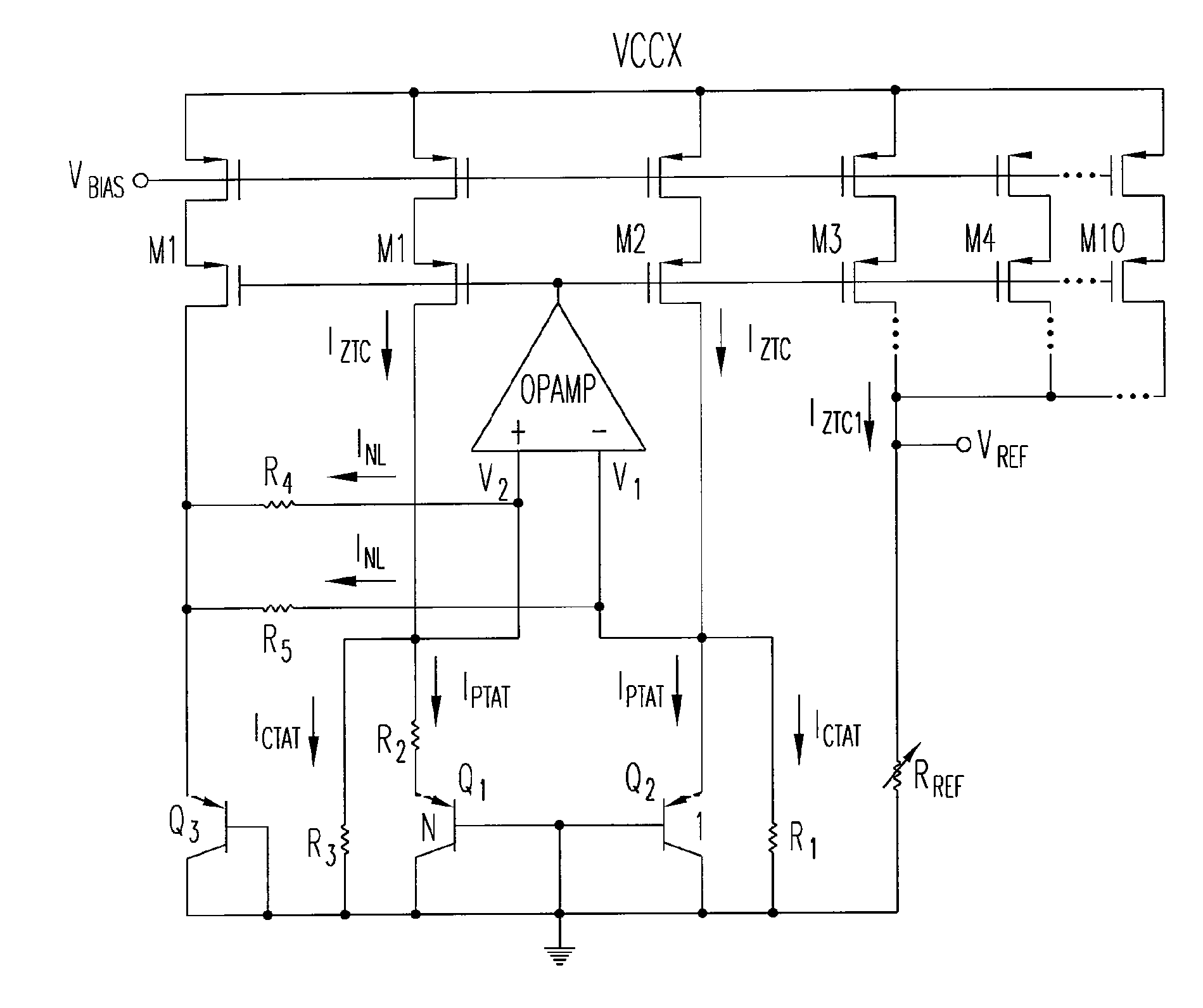
[0031]Disclosed herein is a robust curvature compensated voltage reference to provide an internal supply voltage for low voltage devices. The internal supply voltage has a tunable positive...


PUM


Abstract

A regulated internal power supply and method are provided. According to various embodiments, a regulated internal power supply system includes a DC to DC converter adapted to connect to an external supply voltage. The converter is further adapted to increase voltage level above a level of the external supply voltage. A low pass filter is connected to the DC to DC converter, and a current-mode bandgap voltage reference (BVR) is connected to the low pass filter. The BVR is adapted to provide second order curvature correction and to provide a tunable voltage reference gradient with respect to the external supply voltage. A power amplifier is connected to the BVR and to a circuit die, to provide a stable internal supply voltage to the die. Other aspects and embodiments are provided herein.

Description

[0001]This application claims priority under 35 U.S.C. 119 from Singapore Application No. 200600373-5 filed Jan. 19, 2006, which application is incorporated herein by reference.TECHNICAL FIELD[0002]This disclosure relates to electrical circuits, and more particularly, to regulated power supplies.BACKGROUND[0003]Many analog and digital circuits require a stable, regulated power supply to generate predictable and repeatable performance. However, it is becoming increasingly difficult to integrate a regulator into a die as power supply voltage levels decrease for modem integrated circuits. For example, first generation Double Data Rate Synchronous Dynamic Random Access Memory (SDRAM DDR1) devices use a 2.5 Volt supply voltage and second generation devices (SDRAM DDR2) use a 1.8 Volt supply. These DDR2 SDRAM devices have a supply voltage at 1.8 Volts and internal circuitries that are designed to work using a 1.8 Volt supply voltage. Thus, no extra voltage headroom is available for use of...

Claims


Application Information

Patent Timeline
Patent Type & Authority Patents(United States)
IPC IPC(8): G05F3/16
CPCH02M1/4225H02M2001/0022H02M2001/007Y02B70/126Y02B70/10H02M1/0022H02M1/007
Inventor HAN, KANG KHENG
Owner APTINA IMAGING CORP
Why Eureka
Try Eureka