
Systems and methods for detecting solenoid armature movement

a technology of solenoid armature and detection system, which is applied in the direction of electric control, magnetic bodies, instruments, etc., can solve the problems of inefficiency and inaccurate detection of system requiring accurate detection of solenoid armature movement under normal operating conditions, and inability to determine when the actuator returns to its original position

Active Publication Date: 2009-01-27
CATERPILLAR INC
View PDF32 Cites 20 Cited by
  • Summary
  • Abstract
  • Description
  • Claims
  • Application Information

AI Technical Summary

Benefits of technology

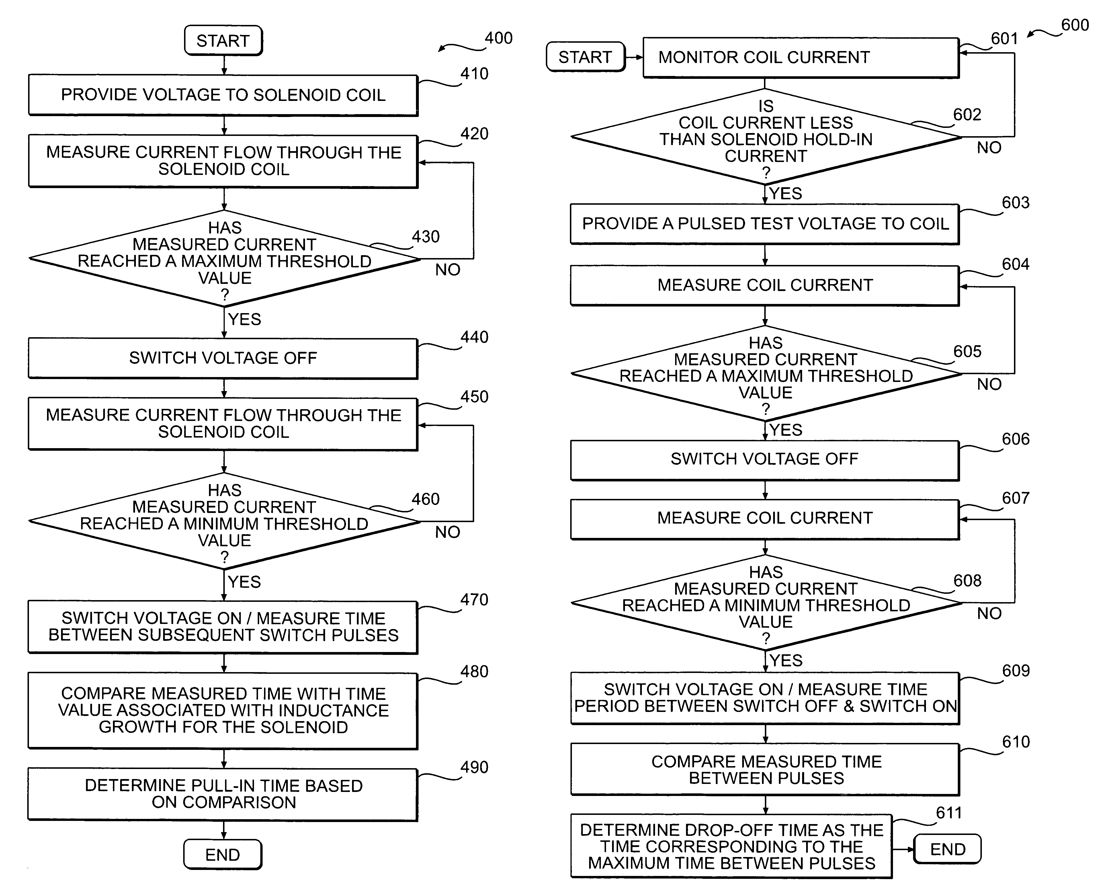
The present patent is directed toward a method and system for detecting the actuation of an armature associated with a solenoid. The method involves measuring the current flowing through the solenoid coil and switching the voltage potential off when the measured current reaches a predetermined maximum value. The system includes a controller that operates the switching elements to selectively provide a pulsed test voltage to the solenoid coil and measures the time period between pulses. By measuring the time period and comparing it to predetermined data, the system can determine the pull-in time of the armature associated with the solenoid. The technical effect of this patent is to provide a more accurate and reliable method for detecting the actuation of the armature and ensuring the proper operation of the solenoid.

Problems solved by technology

Although the system of the '562 patent may determine an erroneous or accidental drop-off of a solenoid armature, it may be problematic.
For example, because the system may only monitor the frequency of the pulsed signal that supplies the hold-in current to detect accidental drop-off, it may not determine when the actuator returns to its original position after the hold-in current has been turned off.
As a result, systems requiring accurate detection of armature movement under normal operating conditions may become inefficient and inaccurate.

Method used


Image

  • Systems and methods for detecting solenoid armature movement
  • Systems and methods for detecting solenoid armature movement
  • Systems and methods for detecting solenoid armature movement

Examples


Embodiment Construction

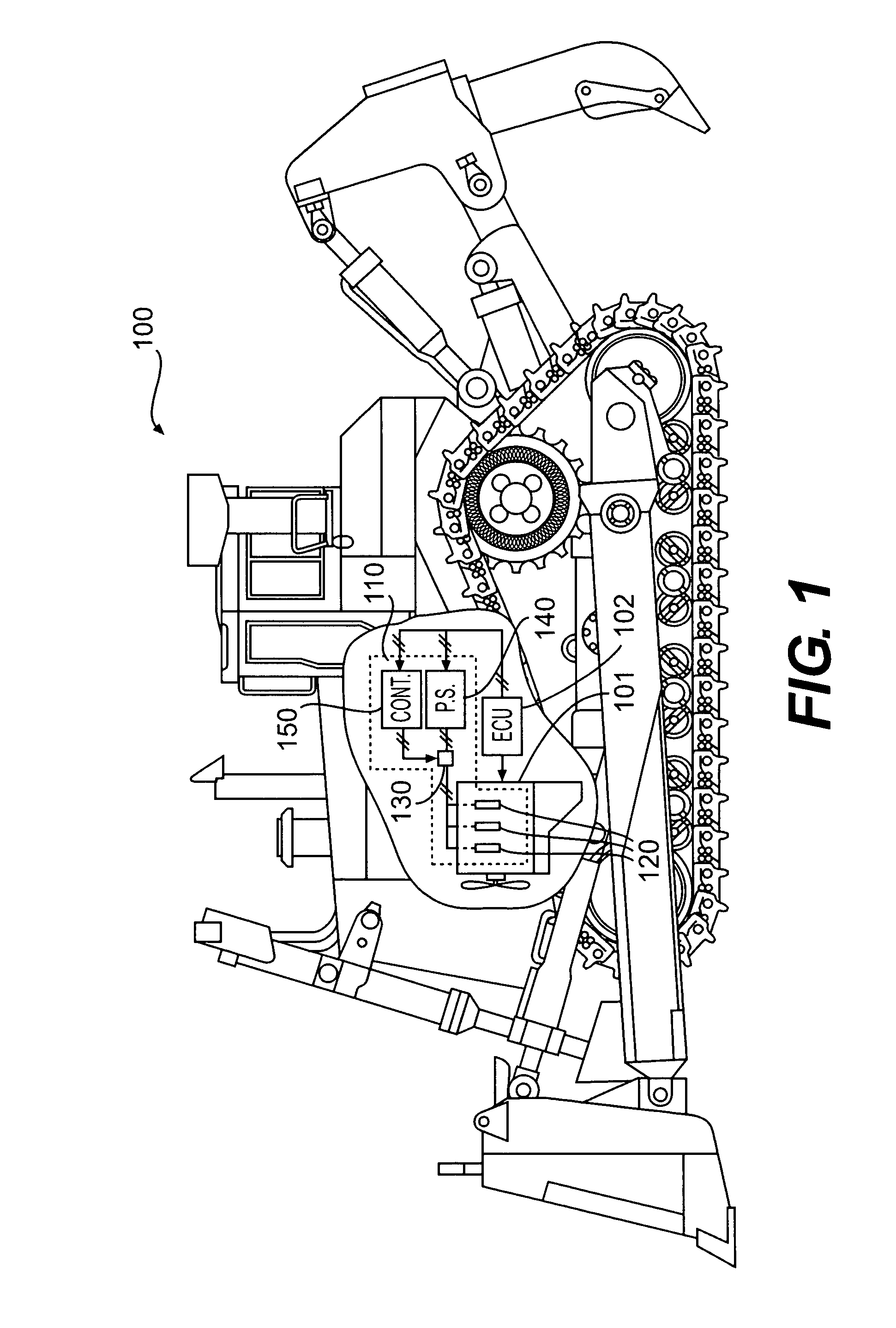
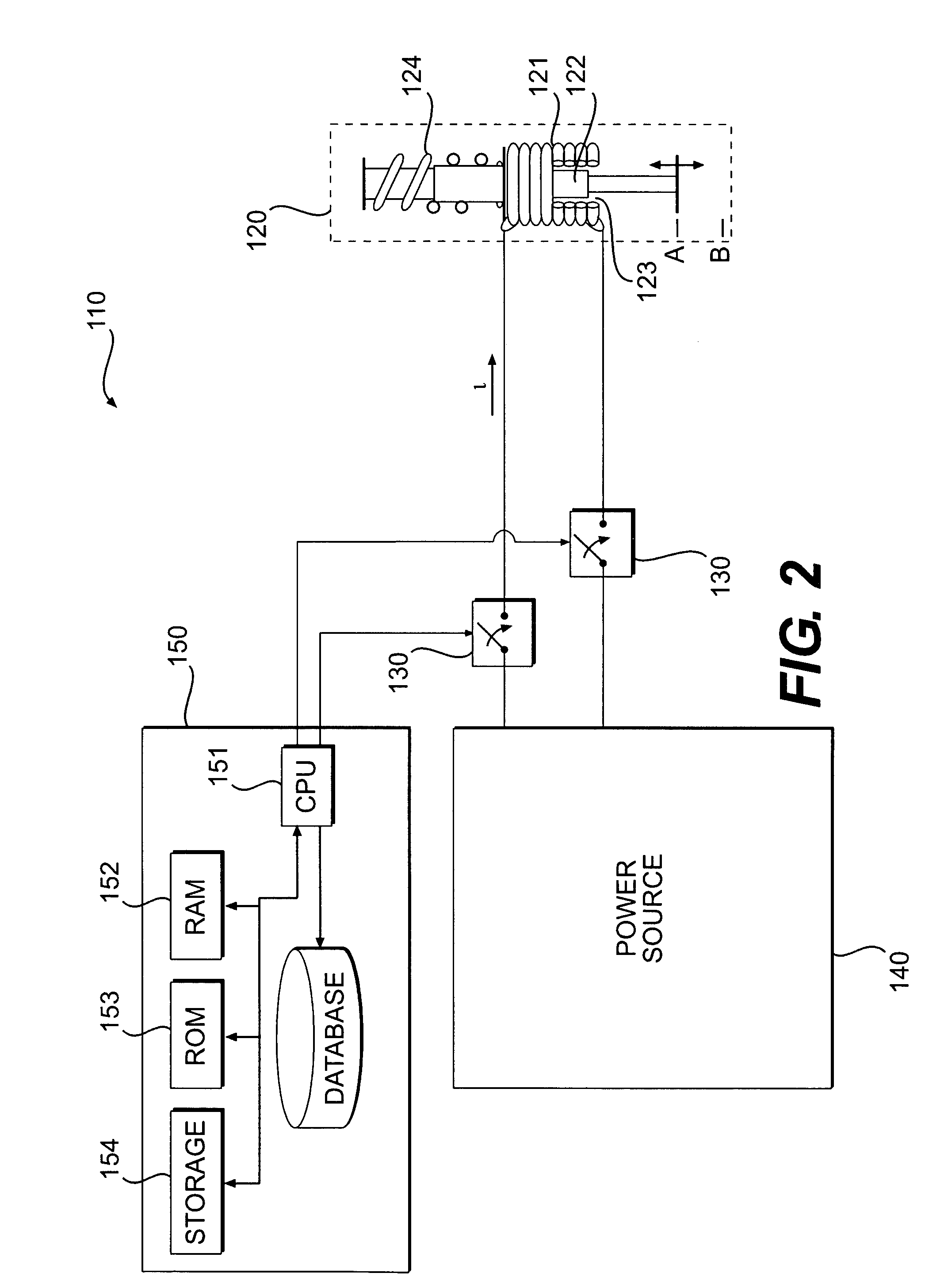
[0021]FIG. 1 provides a diagrammatic illustration of an exemplary machine 100 according to certain disclosed embodiments. Machine 100 may include any fixed or mobile machine for performing a task associated with an industry such as mining, construction, farming, transportation, power generation, manufacturing, and any other type of industry. Non-limiting examples of fixed machines include engine systems, turbines, power generators, stationary drill equipment (e.g., for an off-shore drill platform), and any other types of fixed machines. Non-limiting examples of mobile machines include cranes, haulers, front end loaders, tractors, on and off-highway vehicles, automobiles, excavators, dump trucks, or any other suitable mobile machine. Machine 100 may include, among other things, a power source 101 for producing a power output, an electronic control unit (ECU) 102, one or more solenoids 120 configured to perform at least one task associated with machine 100, and a system 110 for detect...


PUM


Abstract

A method for detecting actuation of an armature associated with a solenoid includes providing a voltage potential to a solenoid coil associated with the solenoid. The method also includes measuring a current flowing through the solenoid coil. The method further includes switching the voltage potential off when the measured current reaches a predetermined maximum value. The method also includes switching the voltage potential on when the measured current reaches a predetermined minimum value. The method further includes measuring a time period between pulses associated with the switching on and off of the voltage potential. The method also includes comparing the measured time period between pulses with predetermined data indicative of an inductance growth level associated with the coil. The method further includes determining, based on the comparison, a pull-in time of an armature associated with the solenoid.

Description

TECHNICAL FIELD[0001]The present disclosure relates generally to armature position detectors and, more particularly, to systems and methods for detecting solenoid armature movement.BACKGROUND[0002]Solenoids are typically classified as any electromagnetic device that converts electrical energy to linear momentum. Solenoids may include a coil conductor wrapped around a metallic piston that serves as an armature. When voltage is applied to the coil terminals, current is passed through the coil conductor generating an electromagnetic field, which draws the metallic piston toward the field. An electronic controller may be coupled to the solenoid for regulating the flow of current through the coil conductor to control the electromagnetic field.[0003]Position of the piston may be manipulated by controlling the strength of the electromagnetic field. For example, in order to initially actuate the solenoid armature, voltage may be applied across the coil conductor, energizing the coil and str...

Claims


Application Information

Patent Timeline
Patent Type & Authority Patents(United States)
IPC IPC(8): H01H47/00G01R31/72
CPCH01F7/1805H01F7/1844G01R31/06H01F2007/185H01F2007/1855H01F2007/1888H01F2007/1894G01R31/72F02D41/20H01H47/22
Inventor SCHUMACHER, JOSEPH WILFRED
Owner CATERPILLAR INC
Learn More