Cooling device for use in an electric arc furnace

a technology of combustion device and electric arc furnace, which is applied in the direction of lighting and heating apparatus, furnace crown/roof, furnaces, etc., can solve the problems of insufficient efficiency, insufficient efficiency of serpentine arrangement, and damage to the furnace itself as well as any device placed inside the furnace, so as to achieve efficient and effective cooling

Inactive Publication Date: 2009-01-27
PROCESS TECH INT
View PDF5 Cites 6 Cited by
  • Summary
  • Abstract
  • Description
  • Claims
  • Application Information

AI Technical Summary

Benefits of technology

[0014]The present invention provides an apparatus for cooling furnace devices that overcomes the deficiencies of the prior art. Preferably, the present invention provides efficient and effective cooling of burners, lances, and related enclosures used in making steel in an electric arc furnace.

Problems solved by technology

In addition to melting the scrap, the electric arc and molten burden can damage the furnace itself as well as any devices placed inside the furnace, such as burners, lances, and enclosures for burners and lances.
While such arrangements are often effective at cooling furnace components, they are not sufficiently efficient and often allow hot spots to develop.
One reason why a serpentine arrangement is not efficient is that as the water flows through the device, small bubbles often form along the walls of the water pipes.
Often, the turbulence of the fluid along the pipe wall is low even when the overall fluid flow through the pipe is high.
While this solution may improve the turbulence of the fluid in a location, it may cause other areas of low turbulence to form.
This may help wash away the bubbles, but it requires significantly higher water flow and pressure, thereby increasing the cost of operations.
Further, certain portions of a furnace device may experience greater heat effects than other portions of the device.
The serpentine structure does not allow a furnace device to receive more cooling in one area than another.
While this solution often works effectively for furnace walls, it is not practical for use in furnace components due to space limitations.

Method used


Image

  • Cooling device for use in an electric arc furnace
  • Cooling device for use in an electric arc furnace
  • Cooling device for use in an electric arc furnace

Examples


Embodiment Construction

[0027]Referring now to the drawings, in which like numerals represent like elements, exemplary embodiments of the present invention are herein described.

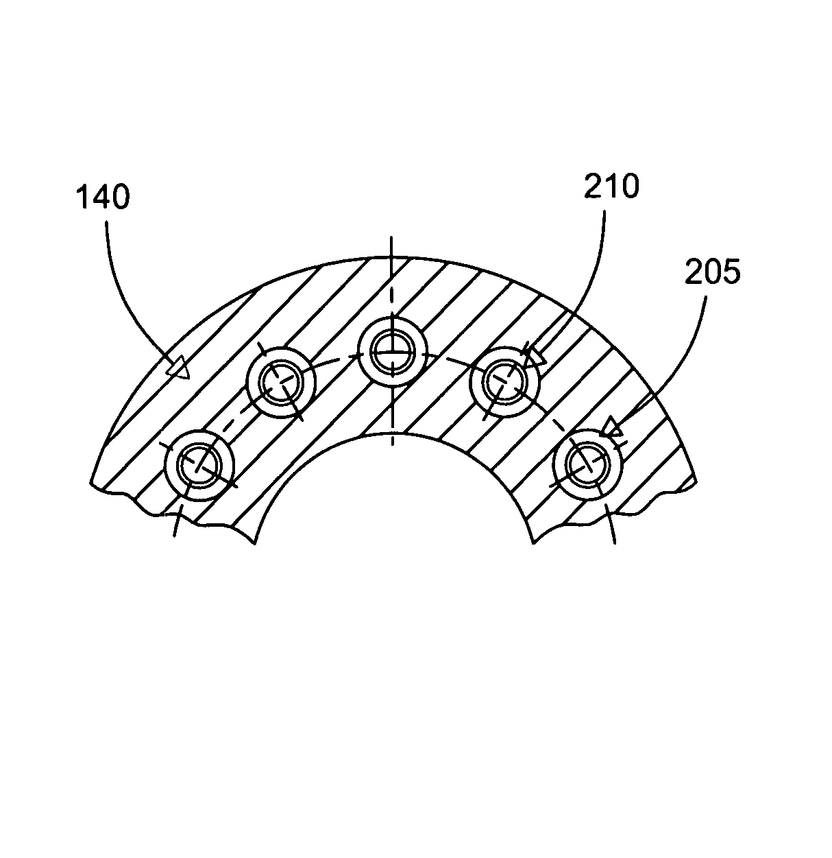
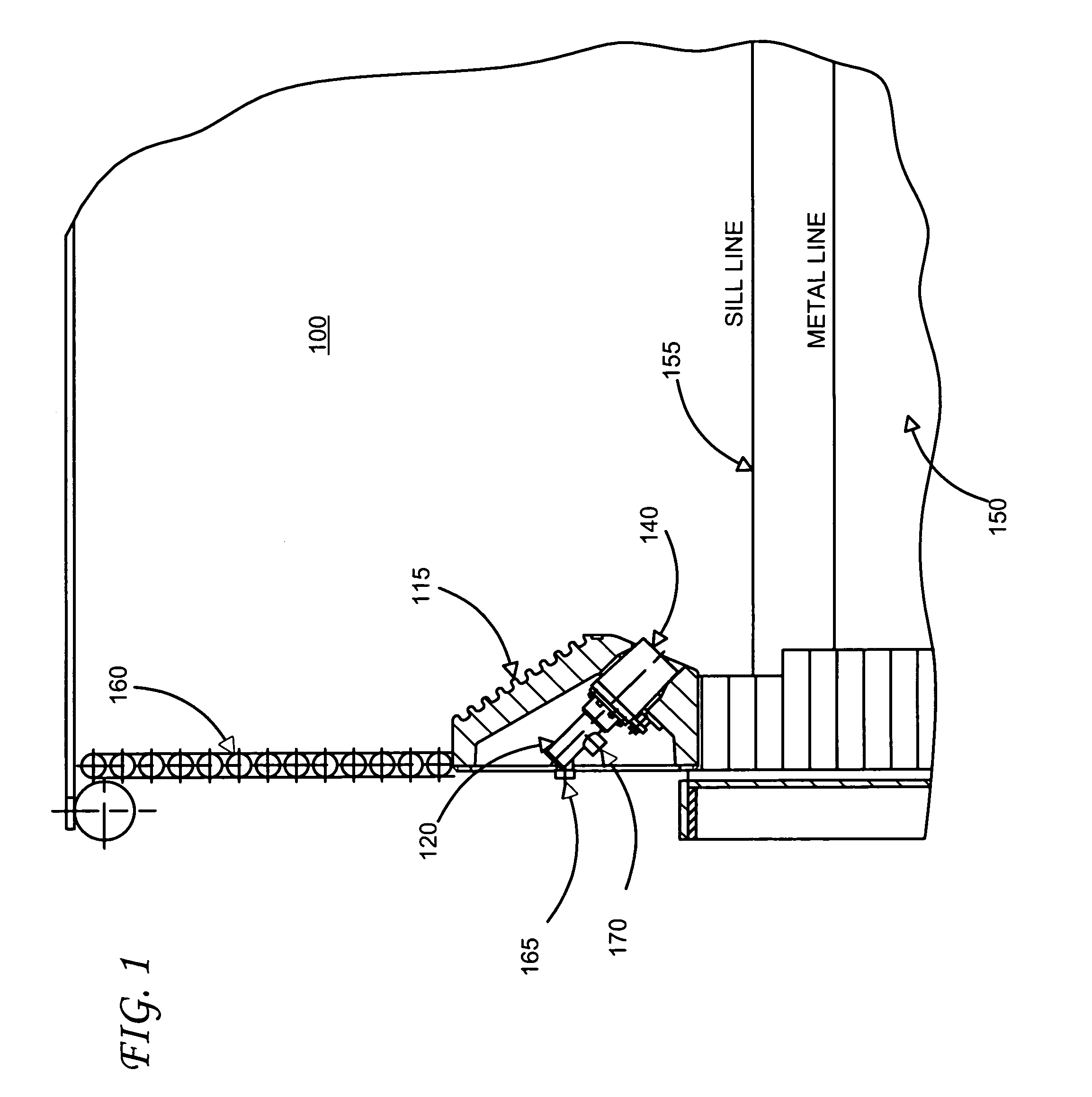
[0028]FIG. 1 is a cross-sectioned side view of an exemplary embodiment a burner mounted in a burner enclosure in an electric arc furnace (“EAF”) and which is constructed in accordance with an exemplary embodiment of the present invention. In an exemplary embodiment, the EAF 100 melts ferrous scrap, or other iron based materials, by means of an electric arc produced from one or more electrodes to collect a molten metal bath or melt 150 in its hearth. The metal bath level varies significantly during the melting process. The bath level generally begins with a hot heel level, which is the iron melt left from the previous heat. As multiple charges of scrap or other iron base materials are melted, the level rises. The furnace is typically filled to a level about 18 inches down from the sill line 155. Other steel making processes such as D...


PUM

PropertyMeasurementUnit
melting pointaaaaaaaaaa
temperatureaaaaaaaaaa

Abstract

A cooling device for use in an electric arc furnace is provided. The cooling device provides a novel and effective method for cooling burners, lances, enclosures, and other devices used in high heat environments, such as in Electric Arc Furnaces. According to one aspect of the invention used in a steel making process in an electric arc furnace, a cooling tube is inserted into a cooling cavity in a burner. Cooling fluid is injected through the cooling tube into the cavity to cool the portions of the burner adjacent the cooling cavity. The cooling fluid is then extracted from the cavity through a concentric space between the cooling tube and the cooling cavity. According to another aspect of the present invention, a cooling fluid distribution flange is provided to distribute cooling fluid to a plurality of cooling tubes to inject cooling fluid into a plurality of associated cooling cavities.

Description

TECHNICAL FIELD[0001]The present invention relates generally to a method and apparatus used in metal melting, refining and processing, and more particularly, a method and apparatus for cooling combustion devices in a metal melting furnace.BACKGROUND[0002]Electric arc furnaces (EAFs) make steel by using an electric arc to melt one or more charges of scrap metal, hot metal, iron based materials, or other meltable materials, which is placed within the furnace. Modern EAFs may also make steel by melting DRI (direct reduced iron) combined with the hot metal from a blast furnace. In addition to the electrical energy of the arc, chemical energy is provided by auxiliary burners using fuel and an oxidizing gas to produce combustion products with a high heat content to assist the arc.[0003]If the EAF is used as a scrap melter, the scrap burden is charged by dumping it into the furnace through the roof opening from buckets, which also may include charged carbon and slag forming materials. A si...

Claims


Application Information

Patent Timeline
Patent Type & Authority Patents(United States)
IPC IPC(8): F27D1/12
CPCC21C5/5211F27B3/205F27B3/22F27B3/24F27D1/12F27D9/00F27D99/0033Y02P10/20
Inventor SHVER, VALERY
Owner PROCESS TECH INT
Why Eureka
Try Eureka