System and method for radio receiver RF background noise estimation

a radio receiver and background noise technology, applied in the field of electromagnetic signal analysis, can solve the problems of inaccuracy of estimates, difficult to predict the impact of targeted receivers, and sometimes more difficult to determine noise values (n)

Inactive Publication Date: 2009-01-27
ARMY US SEC THE THE
View PDF14 Cites 16 Cited by
  • Summary
  • Abstract
  • Description
  • Claims
  • Application Information

AI Technical Summary

Benefits of technology

[0016]The invention has several advantages. The invention provides a coherent and reasonable method of estimating the RF noise environment for any given radio receiver. Moreover, experimental tests have studied the validity of the invention's method, and have found that the resulting values of the RF noise determined by the invention have been accurately and, in some cases; exactly predicted. For example, the RF noise estimation process provided by the invention may be applied to GPS systems to predict the maximum receiver S / N. In fact, experimental testing in this environment has been successful, as the estimate of N was determined to be correct.

Problems solved by technology

The problem that arises is once the received signal level is calculated, the S / N ratio must be determined since it is used directly or, in the case of digital communications, it is used to find the digital link bit error rate (BER) from the known input S / N versus bit error rate relationship characteristic of the radio being portrayed by the model.
In some cases these guesses are fairly soundly based, and other times just based on the user's intuition, which results in inaccurate estimates.
However, when the radiated jammer signal is in the form of an instantaneous jammer signal of a given bandwidth swept across the targeted frequency spectrum, the affect on the targeted receivers is much more difficult to predict.
However, the noise value (N) is sometimes more difficult to determine.

Method used


Image

  • System and method for radio receiver RF background noise estimation
  • System and method for radio receiver RF background noise estimation
  • System and method for radio receiver RF background noise estimation

Examples


Embodiment Construction

[0043]The invention and the various features and advantageous details thereof are explained more fully with reference to the non-limiting embodiments that are illustrated in the accompanying drawings and detailed in the following description. It should be noted that the features illustrated in the drawings are not necessarily drawn to scale. Descriptions of well-known components and processing techniques are omitted so as to not unnecessarily obscure the invention. The examples used herein are intended merely to facilitate an understanding of ways in which the invention may be practiced and to further enable those of skill in the art to practice the invention. Accordingly, the examples should not be construed as limiting the scope of the invention.

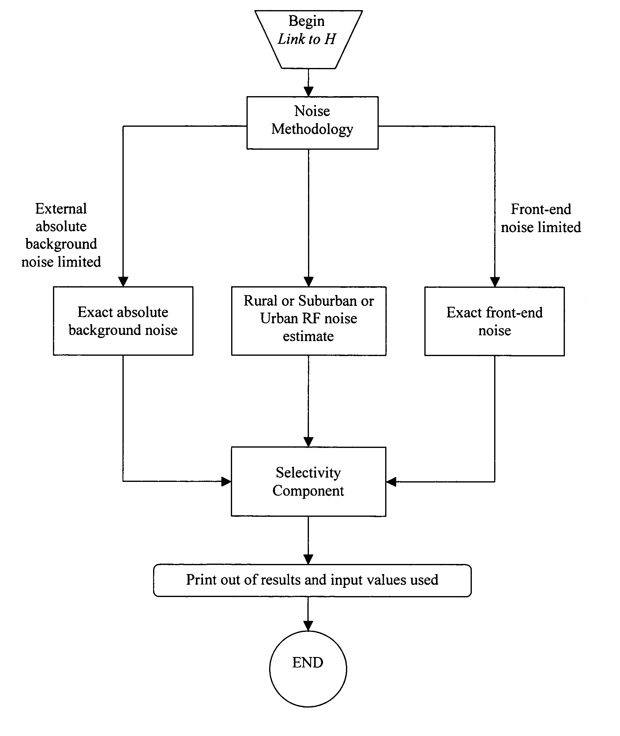
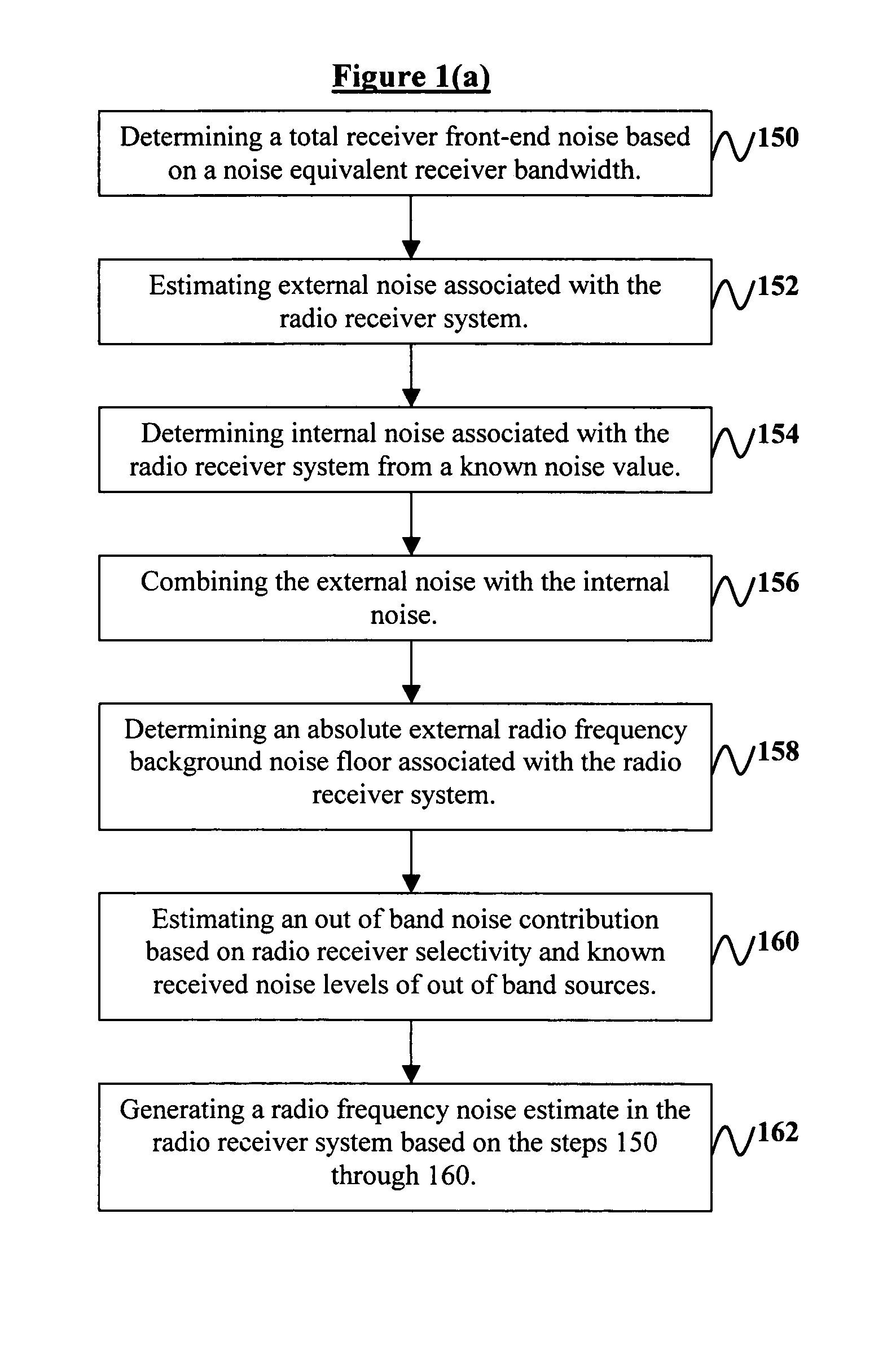
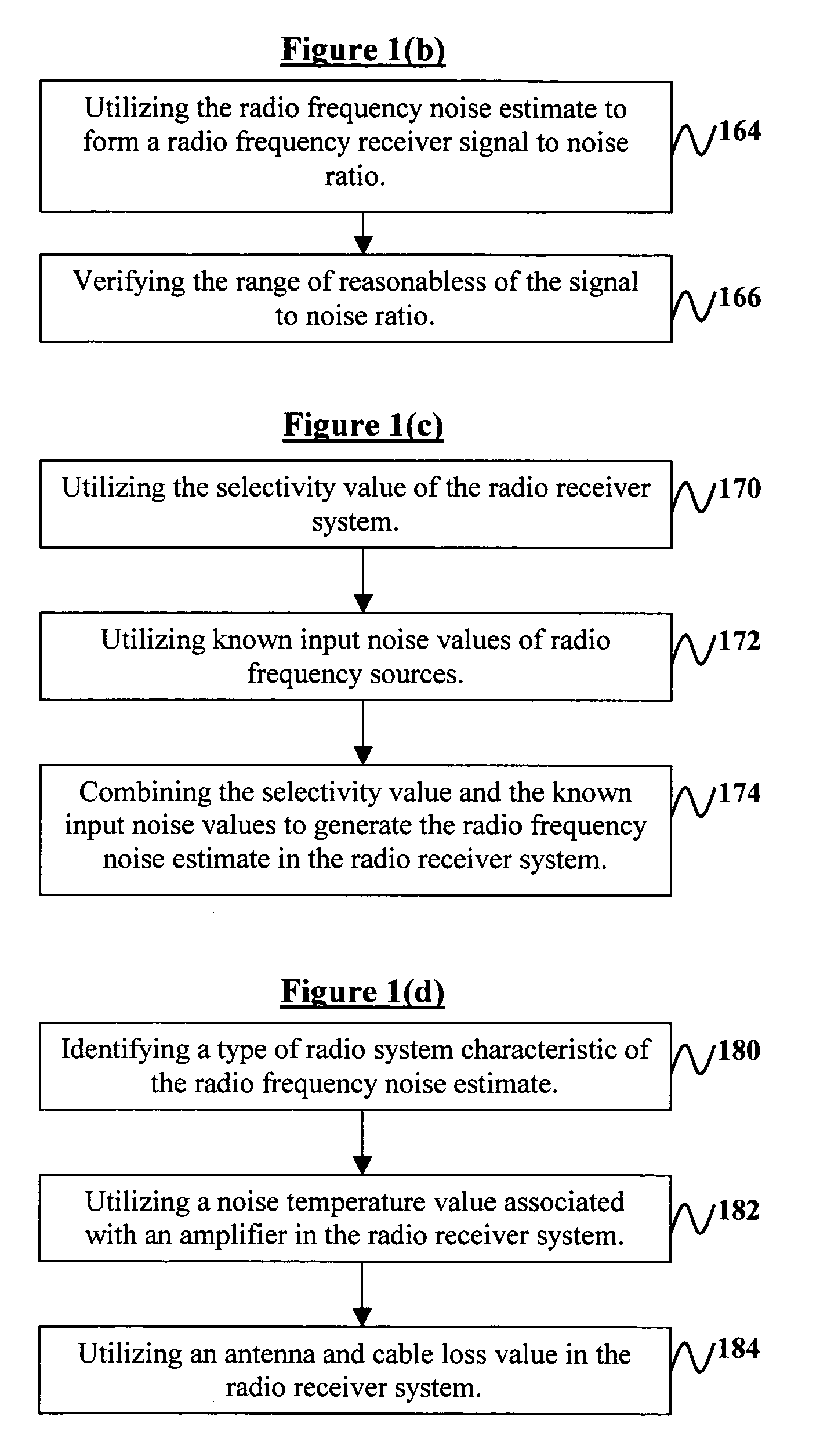
[0044]As previously mentioned, there is a need for a system and method of determining where the ambient noise estimate is generated from and how it affects estimating the expected performance of radio frequency radio links. Referring now t...


PUM


Abstract

A system and method of estimating radio frequency (RF) background noise in a radio receiver system comprises determining a total receiver front-end noise based on a noise equivalent receiver bandwidth; estimating external noise associated with the radio receiver system; determining internal noise associated with the radio receiver system from a known noise value; combining the external noise with the internal noise; determining an absolute external (RF) background noise floor associated with the radio receiver system; estimating an out of band noise contribution based on radio receiver selectivity and known received noise levels of out of band sources; and generating a (RF) noise estimate in the radio receiver system based on the above steps. The invention utilizes the (RF) noise estimate to form a (RF) receiver signal to noise ratio enabling an estimate performance of (RF) radio links in the radio receiver system operating in a benign and hostile (RF) environment.

Description

GOVERNMENT INTEREST[0001]The invention described herein may be manufactured, used, and / or licensed by or for the United States Government.BACKGROUND OF THE INVENTIONField of the Invention[0002]The invention generally relates to electromagnetic signal analysis, and more particularly to estimating the expected performance of radio frequency signals in various radio frequency environments.DESCRIPTION OF THE RELATED ART[0003]In many conventional computer program models, which are used to make an estimate of the expected performance of a given communications system operating in a real world radio frequency (RF) environment or in the presence of intentional or unintentional interference, a receiver signal to noise ratio (S / N) is first calculated. This is usually performed by first locating the transmitter on a digital terrain surface and using that digital terrain surface to compute the received signal at some other point located on that surface by calculating signal level loss.[0004]The ...

Claims


Application Information

Patent Timeline
Patent Type & Authority Patents(United States)
IPC IPC(8): H03D1/04
CPCH04B17/345
Inventor MICHAELS, JR., PAUL A.
Owner ARMY US SEC THE THE
Why Eureka
Try Eureka