Supercharge Your Innovation With Domain-Expert AI Agents!

Method and apparatus for sampling a power supply current of an integrated circuit, and storage medium onto which is recorded a control program therefor

a power supply current and integrated circuit technology, applied in the field of integrated circuit test technology, can solve the problems of incomplete power supply current information for the power supply current flowing in the integrated circuit under test (dut), and achieve the effect of completely obtaining the device under tes

Inactive Publication Date: 2009-01-27
RENESAS ELECTRONICS CORP
View PDF21 Cites 4 Cited by
  • Summary
  • Abstract
  • Description
  • Claims
  • Application Information

AI Technical Summary

Benefits of technology

Enables the acquisition of accurate and complete power supply current information, including post-test signal stabilization, thereby improving the reliability of frequency spectrum analysis.

Problems solved by technology

In the method described in the above-noted reference, however, there is a problem that there exists a possibility that the power supply current information for the power supply current flowing in the integrated circuit under test (DUT; device under test) is not completely obtained.

Method used


Image

  • Method and apparatus for sampling a power supply current of an integrated circuit, and storage medium onto which is recorded a control program therefor
  • Method and apparatus for sampling a power supply current of an integrated circuit, and storage medium onto which is recorded a control program therefor
  • Method and apparatus for sampling a power supply current of an integrated circuit, and storage medium onto which is recorded a control program therefor

Examples


first embodiment

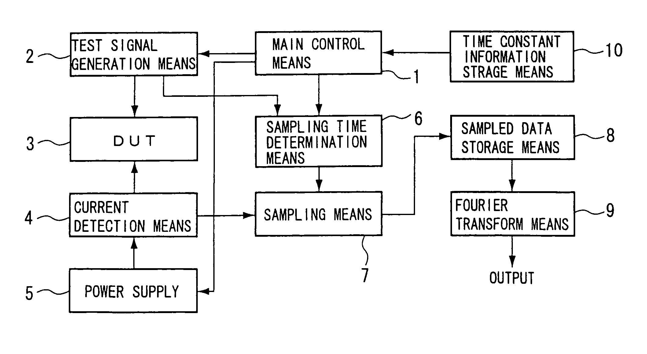
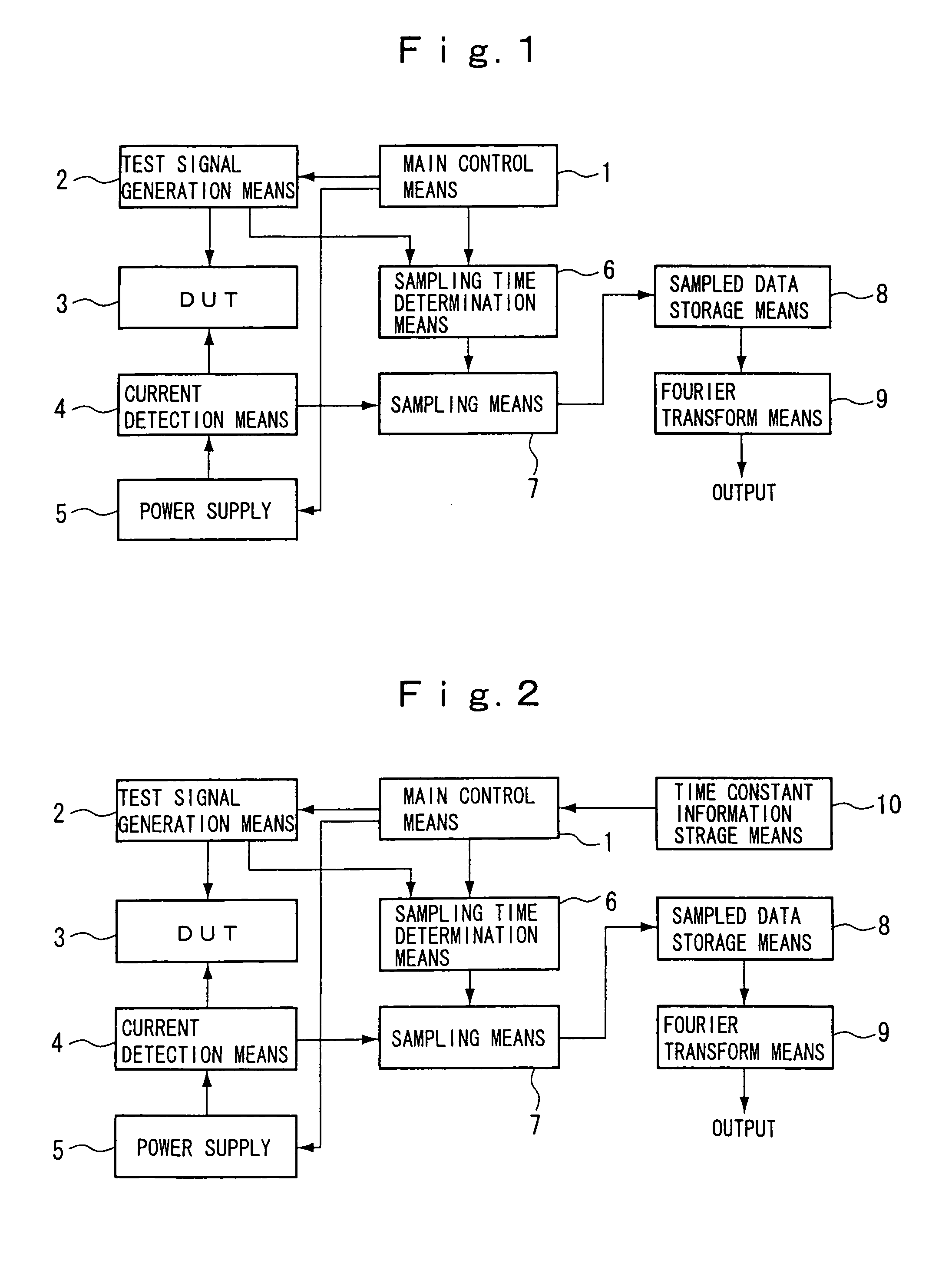
[0077]The operational effect of the present invention is described below, with reference made to FIG. 1. Because sampling of a power supply current value signal in the past was ended simultaneously with the end of application of the test signal to the DUT 3, the sampled power supply current value signal, as indicated by the sampled data A, was cut off at time B. However, because the circuitry making up the power supply, the current detection means, and the DUT has a bypass capacitors for the purpose of stabilizing the power supply voltage applied to the DUT, capacitance and inductance internal to the power supply and parasitic capacitances and the like, there is a certain time constant in the circuitry. This time constant means that even after the application of the test signal to the DUT is ended (at time B) and the DUT operation stops, there is a power supply current detected by the current detection means, the flow of this current stopping (or stabilizing) when a certain amount o...

second embodiment

[0084]The operational effect of the present invention is described below.

[0085]The time constant of the circuitry making up the power supply, the current detection means, and the DUT varies depending on the type of power supply and DUT. Given this situation, the time constant is determined and stored for each DUT, making it possible to immediately obtain the time constant information for each circuit system made up of a power supply, a current detection means, and a DUT. The amount of time required for the power supply current to stop or stabilize after stopping the application of a test signal is determined by the time constant of the circuitry. Because of this, by establishing the time extension of sampling of the power supply current value signal based on the time constant information of the particular circuit, it is possible to easily obtain an accurate frequency spectrum of the power supply current.

[0086]A third embodiment of the present invention is described below. FIG. 3 is ...

third embodiment

[0093]The operational effect of the present invention is as follows.

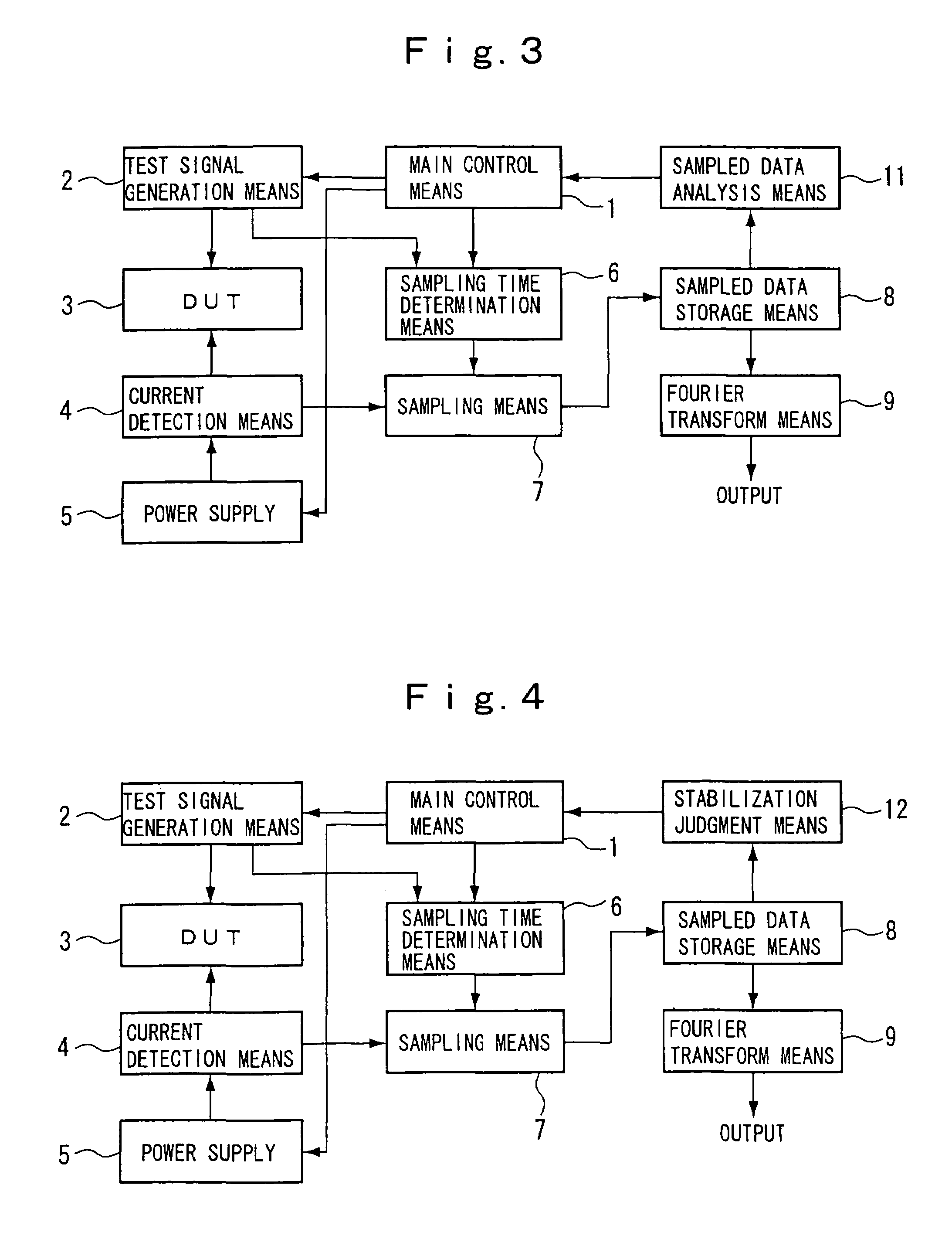
[0094]The sampling extension time for the sampling of the power supply current value signal is determined by the time constant of the circuitry formed by the power supply, the current detection means, and the DUT. If this time constant is not known with certainty, however, it is not known with certainty how much time the sampling should be extended to obtain accurate capture of the power supply current information. Given this, sampling is performed one time of the power supply current value signal over a sufficient amount of time and the sampled results are analyzed, so as to determine how much time the sampling should be extended in order to obtain accurate power supply current information. That is, in the third embodiment it is possible to reliably obtain power supply current information without knowing the precise time constant of the circuitry.

[0095]Next, a fourth embodiment of the present invention is described...


PUM


Abstract

An apparatus for sampling a power supply current value for performing frequency analysis of the power supply current flowing in an integrated circuit with a test signal applied to the integrated circuit has a power supply generating a prescribed supply of power for the integrated circuit (DUT: device under test), a current detection means for observing the power supply current value supplied from the power supply to the DUT, a test signal generation means for generating a prescribed test signal to be applied to an input / output terminal other than a power supply terminal of the DUT and for generating a test signal application signal during application of the test signal to the DUT, a sampling means for sampling the power supply current value signal, a sampling time determining means for instructing the sampling means with regard to the start and end timing for sampling, based on the test signal application signal, a sampling data storage means for storing data sampled by the sampling means, a Fourier transform means for performing a Fourier transformation calculation on the sampled data, and a main control means for outputting instructions to various other means and performing overall apparatus control.

Description

CROSS-REFERENCE TO RELATED PATENT APPLICATIONS[0001]This application is a division of Application Ser. No. 09 / 796,451 filed Mar. 2, 2001, now pending, and based on Japanese Application No. 2000-59090, filed Mar. 3, 2000 by Kazuhiro Sakaguchi. This application claims only subject matter disclosed in the parent application and therefore presents no new matter.BACKGROUND OF THE INVENTION[0002]1. Field of the Invention[0003]The present invention relates to test technology for an integrated circuit, and more particularly to a method and apparatus for sampling a power supply current for performing frequency analysis of the power supply current flowing in the integrated circuit when a test signal is applied thereto, and to a storage medium onto which is stored a control program for controlling the sampling apparatus.[0004]2. Related Art[0005]A method such as noted above of sampling the power supply current of an integrated circuit was used in the past in order to perform frequency spectrum...

Claims


Application Information

Patent Timeline
Patent Type & Authority Patents(United States)
IPC IPC(8): G06F19/00G01R23/16G01R19/00G01R31/26G01R27/28G01R31/28G01R31/30G01R31/319G01R31/3193
CPCG01R31/31935G01R31/3004
Inventor SAKAGUCHI, KAZUHIRO
Owner RENESAS ELECTRONICS CORP
Features
  • R&D
  • Intellectual Property
  • Life Sciences
  • Materials
  • Tech Scout
  • Unparalleled Data Quality
  • Higher Quality Content
  • 60% Fewer Hallucinations
Learn More