Separator device

Active Publication Date: 2009-02-03
NIJHUIS WATER TECH
View PDF13 Cites 10 Cited by
  • Summary
  • Abstract
  • Description
  • Claims
  • Application Information

AI Technical Summary

Benefits of technology

[0017]It is also known to utilise in a separator device for air floatation, as a flow element a stack of parallel, corrugated plates, defining flow channels for separation of the fractions in the mixture. The stack of plates is inclined at an angle of about 60 degrees with the horizontal. In the known air floatation device, air is dissolved under pressure in the range of 300 to 600 kPa in a recycled water stream. Just before the aerated water is mixed with waste water, containing floatable matter (oil, grease or floc) the pressure is released to produce a large number of small air bubbles which adhere to the pollutants and assist these pollutants to separate from the mixture in an upward direction in the flow element.
[0019]By forming a two-dimensional array of enclosed flow channels, according to the present invention, the channels have a decreased hydraulic diameter, and hence a lower Reynolds number. The small hydraulic diameter allows the Reynolds number of the flow element of the present invention to remain low during operation which means that laminar flow conditions can be maintained even at high flow rates, while maintaining a favourable upwards rise rate of air bubbles and floatable material entrained by the bubbles through the flow channels. Hence the flow rate can be increased in the floatation device of the present invention while maintaining proper separation.
[0026]By use of a level controlled valve, a separate effluent compartment and overflow weir can be omitted, allowing additional room in the separator device for additional flow channels, hence increasing the capacity of the unit. Another advantage of using a level controlled valve for removal of treated substance from the separator device, is that a fixed fluid level is obtained which is independent of the flow rate. This in contrast to the use of an overflow weir, which produces a higher level at higher flow rates. Furthermore, the level controlled valve allows an increase in fluid level at the end of a cycle to discharge all floated matter before shut down.

Problems solved by technology

The known device has as a disadvantage that floatable solid or liquid fractions, such as for instance grease or oil, of the mixtures which do not tend to form sediment cannot be effectively separated.

Method used


Image

  • Separator device
  • Separator device
  • Separator device

Examples


Embodiment Construction

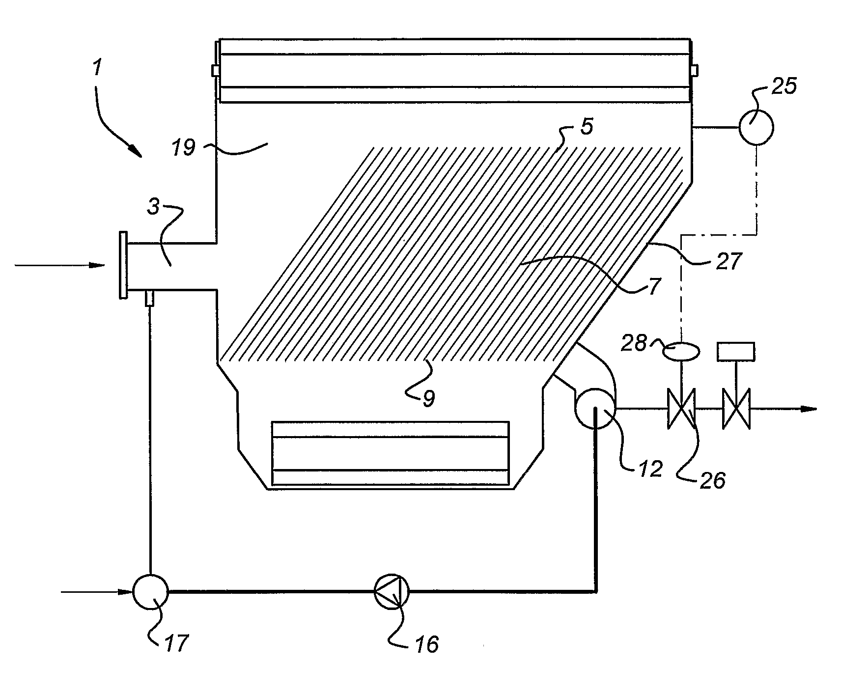
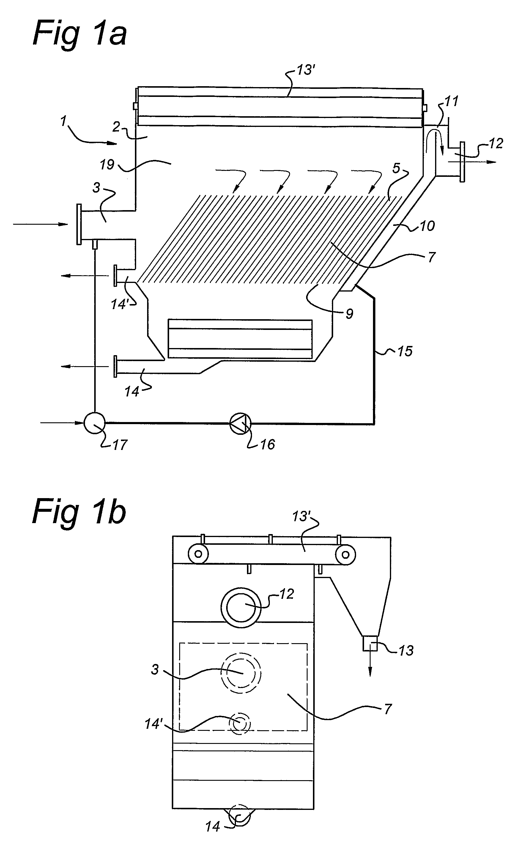
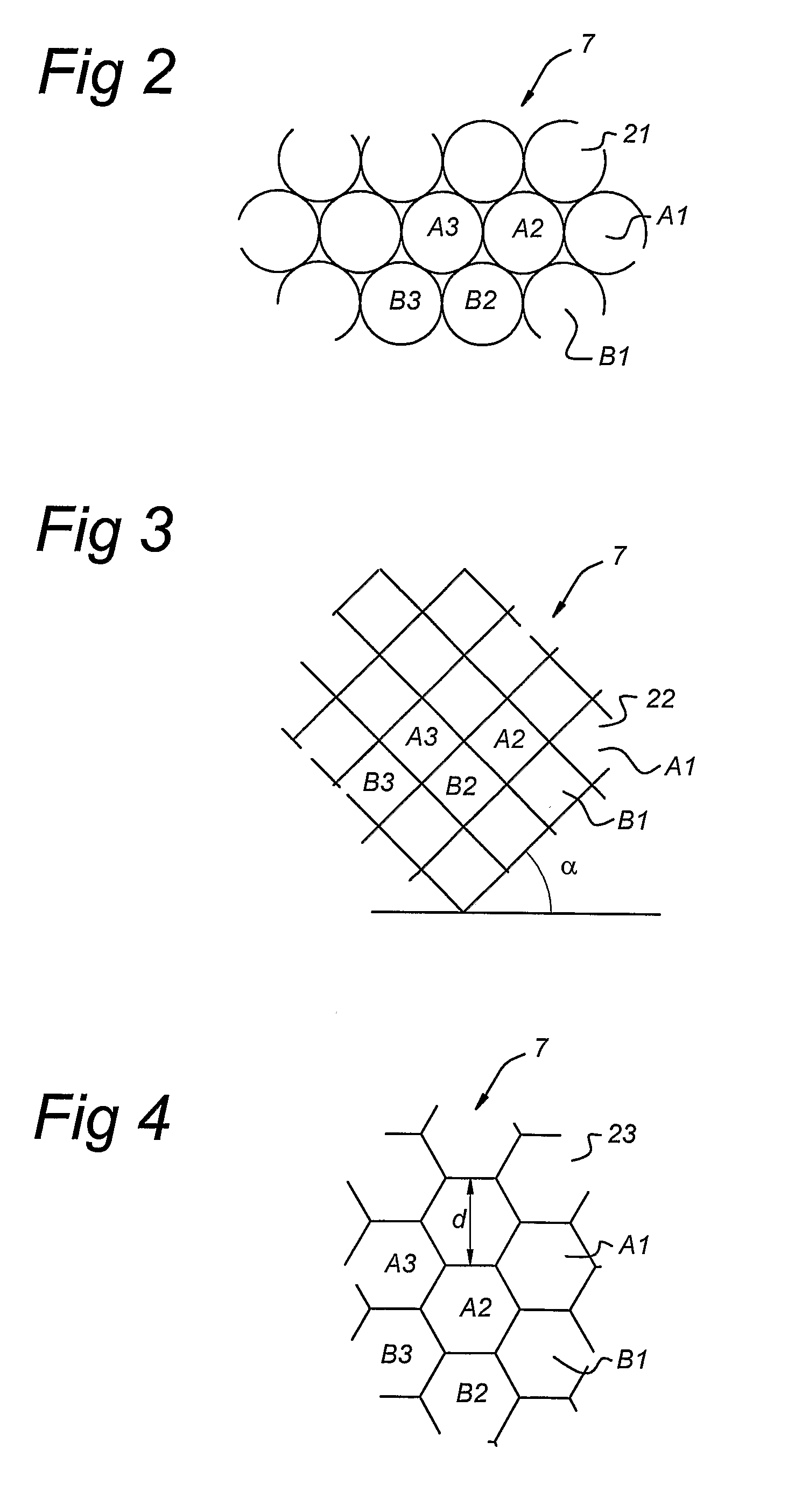
[0031]FIG. 1 shows a separator device 1, with an inlet 3 for receiving a mixture of substances, such as waste water. The mixture flows to an inlet end 5 of a flow element 7. The flow element 7 is schematically indicated in this figure, and comprises a 3-dimensional array of parallel flow channels. The flow channels are oriented at an angle to the horizontal, for instance at a slanting angle of 60°. From an outlet end 9 of the flow element 7, a first fraction of the mixture, such as water, flows through an upwardly extending channel 10 to an overflow weir 11, and from there to a first outlet 12. The second fraction, such as oil, grease or solids, is collected in compartment 19 and is discharged via a transport belt 13′ through second outlet 13, shown in FIG. 1B. Heavy debris, such as sand, may be discharged through outlet 14. The separator device may be drained via outlet 14′. A return duct 15 is attached to the lower end of channel 10 and is via pump 16 connected to air mixing devic...


PUM

PropertyMeasurementUnit
Angleaaaaaaaaaa
Lengthaaaaaaaaaa
Lengthaaaaaaaaaa

Abstract

The invention relates to a separator device for separating a first liquid substance from a second substance, the two substances forming a mixture. The apparatus comprises a vessel with an inlet for receiving the mixture, a first outlet for discharge of a first fraction of the mixture, a second outlet for discharge of a second fraction of the mixture and a flow element. The flow element comprises a number of parallel tubular channels defining a flow path for the mixture, the channels having an gilet end for receiving the mixture and an outlet end for discharge of the first fraction, a length direction of the channels being inclined with respect to a horizontal direction, wherein in a transverse cross section through the flow element, the channels form a two-dimensional array of closed cells, each cell defining a boundary of a flow channel, the cells being arranged in at least two rows, each cell in a first row contacting with its perimeter a cell in the second row. The device comprises a return duct from a first outlet to the inlet via a gas mixing device.

Description

BACKGROUND OF THE INVENTION[0001]1. Field of the Invention[0002]The invention relates to a separator device for separating a first liquid substance from a second substance, the two substances forming a mixture, the apparatus comprising:[0003]a vessel with an inlet for receiving the mixture,[0004]a first outlet for discharge of a first fraction of the mixture,[0005]a second outlet for discharge of a second fraction of the mixture, and[0006]a flow element comprising a number of parallel tubular channels defining a flow path for the mixture, the channels having an inlet end for receiving the mixture and an outlet end for discharge of the first fraction, a length direction of the channels being inclined with respect to a horizontal direction, wherein in a transverse cross-section through the flow element, the channels form a two-dimensional array of closed cells, each cell defining a boundary of a flow channel, the cells being arranged in at least two rows, each cell in a first row cont...

Claims


Application Information

Patent Timeline
IPC IPC(8): C02F1/24B01D21/02B01D17/028B01D17/00B01D17/02B01D21/00B03D1/24
CPCB01D17/00B01D21/0018B01D21/0024B01D21/0051B01D21/10B01D21/2433B01D21/2444B01D21/245B01D21/2488B01D21/34C02F1/24B01D17/0205B01D17/0211B01D17/0214B03D1/1475B03D1/1481B03D1/247B03D1/028C02F2209/42B01D21/0084B01D17/12
Inventor EIJT, ANTONIUS CHARTIANUS JOHANNESKLUIT, ARIE
Owner NIJHUIS WATER TECH
Why Eureka
Try Eureka