Automotive heat exchanger assemblies having internal fins and methods of making the same

a heat exchanger and internal fin technology, applied in the field of brazed heat exchangers, can solve the problems of fatigue fracture, fatigue fracture, fatigue fracture of both the tube and the internal fin, and specific fractures, such as transverse fractures, to reduce the ‘contamination’ of charged air and reduce contamination

Active Publication Date: 2009-02-10
VALEO INC
View PDF22 Cites 41 Cited by
  • Summary
  • Abstract
  • Description
  • Claims
  • Application Information

AI Technical Summary

Benefits of technology

[0010]The present invention, in various embodiments, therefore, provides for a heat exchanger assembly with an improved thermal / pressure resistant heat exchanger (e.g. a heat exchanger with an increased thermal durability yielding increased functional life of the heat exchanger assembly), in high pressure and or temperature environments found in after coolers, and, especially, in charge air coolers.
[0034]The present invention also provides, in one aspect, a method for reducing ‘contamination’ of charged air, by, for example, internal fins which typically cleave chips on the inlet side of a CAC due to the high stresses at the inlet tube to header joint. By positioning the tube strengthener in an area of stress, in a tube wall, brazing the tube strengthener as part of the heat exchanger brazing process subsequently reduces contamination from the internal fin, in charge air coolers.

Problems solved by technology

In recent years, the temperatures and pressures of so-called ‘turbo-charged’ air has significantly increased, resulting in failure of heat exchangers such as those of prior art charge air coolers (CACs), and after coolers due to thermal stresses.
In such temperature / pressure conditions, a major disadvantage of prior art designs has been common failures, such as fatigue fracture, of both the tube and the internal fin.
In prior art designs, specific fractures, such as transverse fractures, may occur, for example, at tube locations, and, in particular, at the inlet header of the heat exchangers.
Also, internal fin fracture may occur and lead to contamination in heat exchangers such as the charge air in coolers.
Increasing material thickness, which further drives costs.
Although effective in improving durability, these changes require significant tooling, process change, material cost, and overall costs of producing a durable charge air cooler.

Method used


Image

  • Automotive heat exchanger assemblies having internal fins and methods of making the same
  • Automotive heat exchanger assemblies having internal fins and methods of making the same
  • Automotive heat exchanger assemblies having internal fins and methods of making the same

Examples


Embodiment Construction

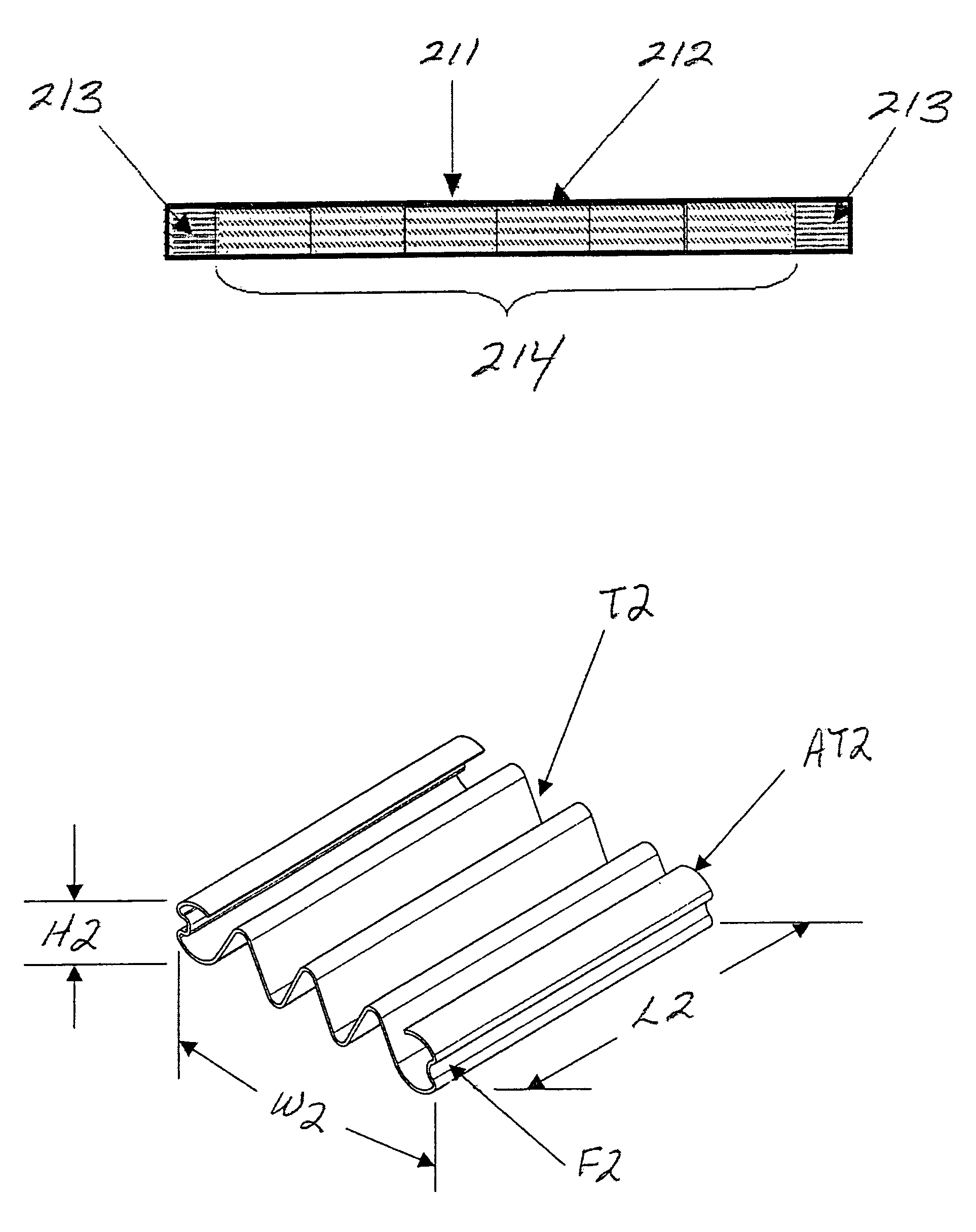
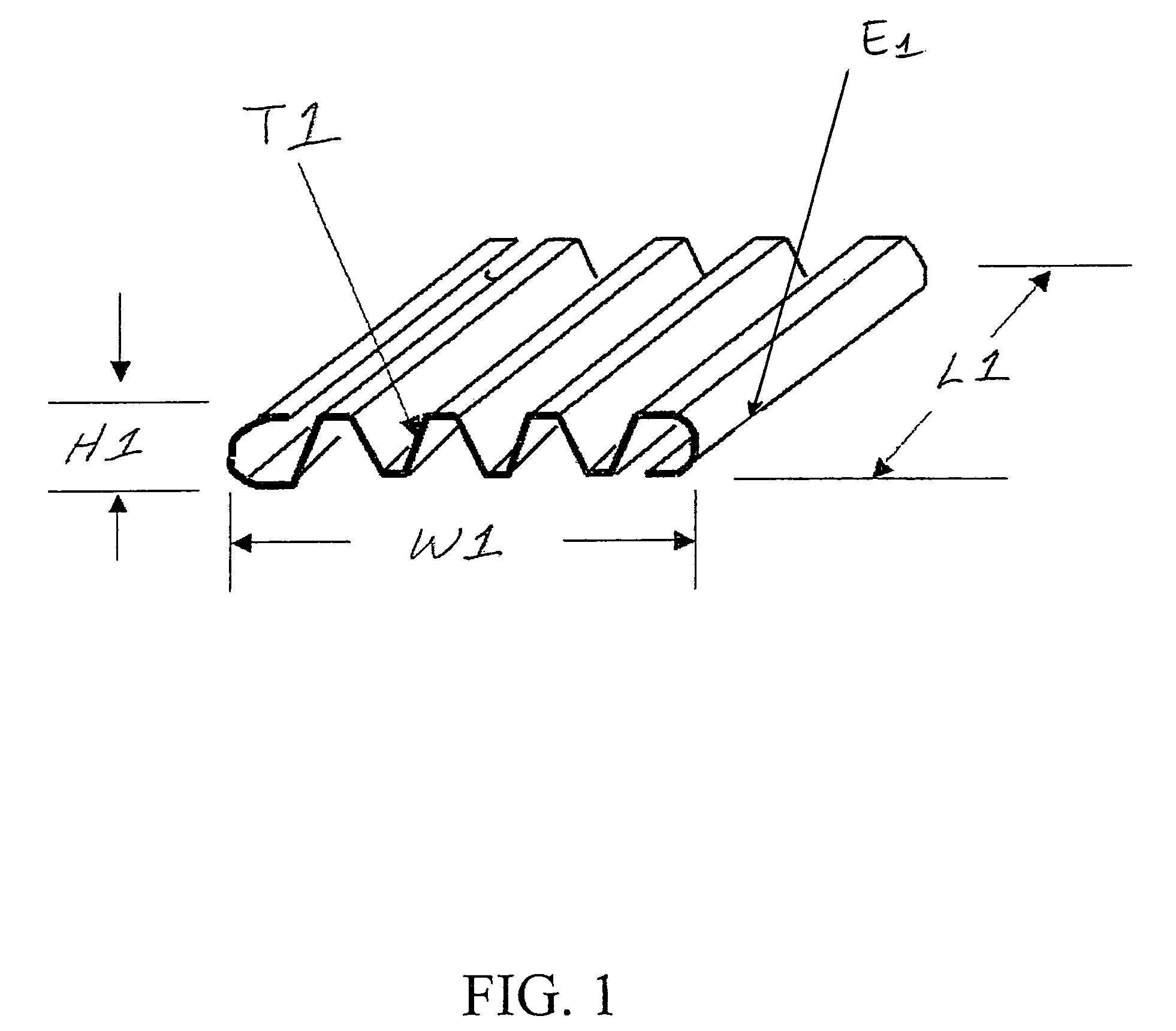
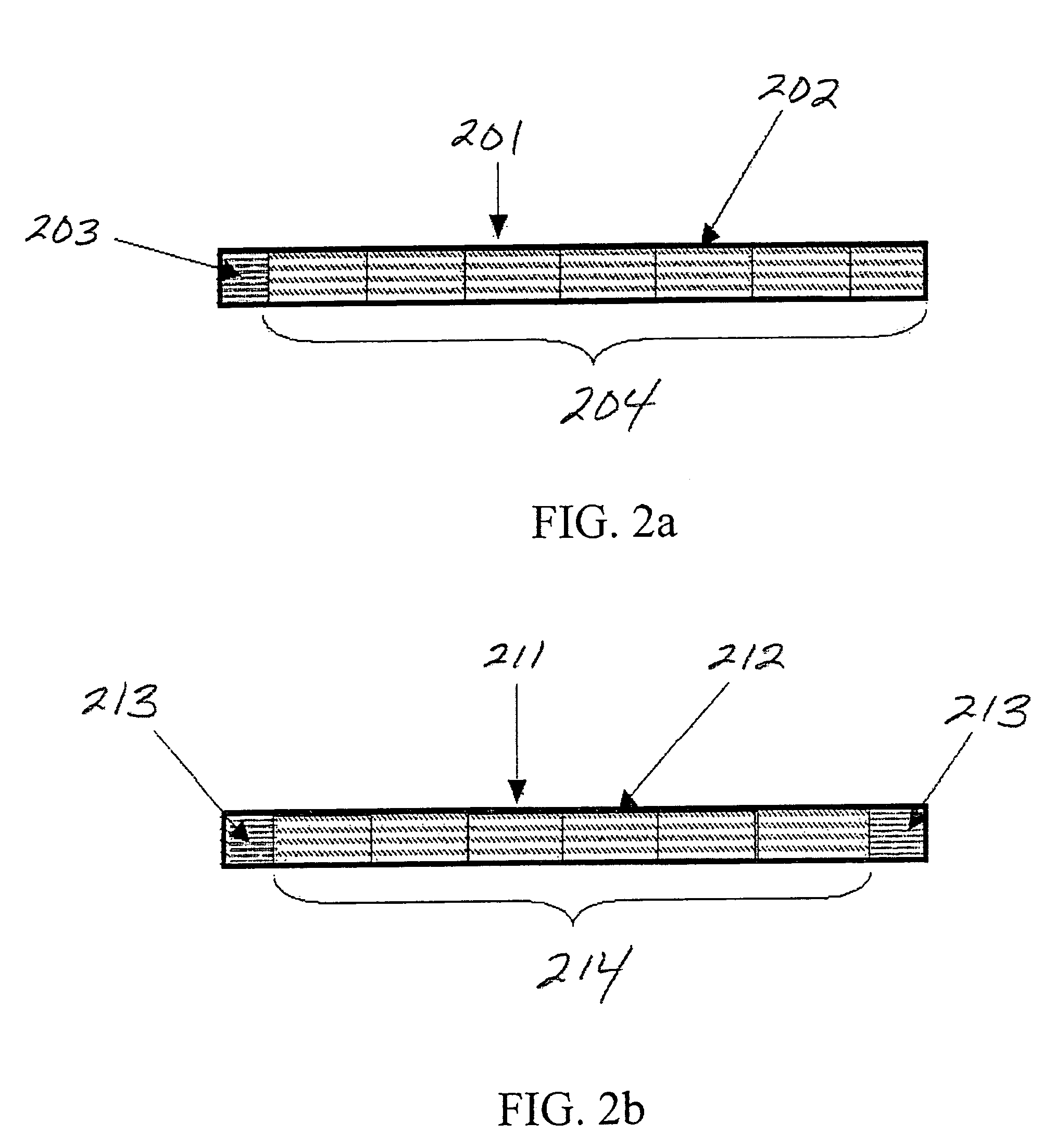
[0050]In aspects of the present invention, there is a heat exchanger assembly comprising: a first end tank; a second end tank opposite the first end tank; at least one first tube in fluid communication with the first and second end tanks, the at one least first tube adapted to have a first fluid flow therethrough, at least one tube strengthener; at least one internal fin; wherein the at least one tube strengthener and the at least one internal fin is positioned inside the at least one tube. In particular embodiments of the present invention, the heat exchanger assembly is brazed. In particular embodiments of the present invention, the at least one tube and the at least one end tank contact each other to form a header joint. Embodiments of the present invention have a tube strengthener that is a tube strengthener-end contact or tube strengthener-structural, or the tube strengthener is a tube strengthener-extruded.

[0051]In some preferred embodiments of the present invention, the modif...


PUM

PropertyMeasurementUnit
lengthaaaaaaaaaa
areaaaaaaaaaaa
strengthaaaaaaaaaa

Abstract

The present invention relates to automotive heat exchanger assemblies that can withstand high environmental temperature and pressures conditions. By providing a tube strengthener inserted into the tubes at the areas of highest stress, the heat exchanger assembly is strengthened to be efficient under typical operating conditions.

Description

[0001]This patent application claims priority of Provisional application 60 / 591,680 filed Jul. 28, 2004.FIELD OF THE INVENTION[0002]The present invention relates to automotive heat exchangers, and, in particular, brazed heat exchangers.BACKGROUND OF THE INVENTION[0003]Various types of heat exchangers are used in automotive applications. For example, WO03093751, published on Nov. 13, 2003, assigned to Behr, relates to a radiator with an internal fin section, and a short section of tube inside the primary tube. In various evaporator applications, as for example illustrated in WO 2004 / 005831, evaporators are shown to be provided with a fin that fits against the tube radius for the full length of the tube.[0004]U.S. Pat. No. 5,105,540 issued on Apr. 21, 1992, to Ford Motor Company shows a tube with an internal liner stock for increasing the interior fluid turbulation. U.S. Pat. No. 4,501,321 issued on Feb. 26, 1985, to Blackstone Corporation shows a two piece tube with the overlap occur...

Claims


Application Information

Patent Timeline
Patent Type & Authority Patents(United States)
IPC IPC(8): F28F9/013F28F9/04
CPCF28F3/025Y10T29/49373Y10S165/906F28F2225/04
Inventor SMITH, PAUL R.IRISH, KELLIE M.LAMANCUSO, SAM J.FREESTONE, KEVIN L.JOHNSON, DAVID S.LYNCH, TERRENCE P.
Owner VALEO INC
Why Eureka
Try Eureka