Mechanically and hydrodynamically operated brewing unit

a hydrodynamic and brewing technology, applied in the field of mechanically and hydrodynamically operated brewing units, can solve the problems of capsule piercing, affecting the quality of the beverage being produced, and increasing the wear-down state of materials

Active Publication Date: 2009-02-10
N& W GLOBAL VENDING
View PDF13 Cites 26 Cited by
  • Summary
  • Abstract
  • Description
  • Claims
  • Application Information

AI Technical Summary

Benefits of technology

[0005]It therefore is the object of the present invention to provide a mechanically and hydrodynamically operated brewing unit for beverage vending machines, which is capable of carrying out the preparation of beverages with the aid of capsules, preferably hermetically sealed ones, containing the raw material to be brewed, while doing away with the drawbacks and disadvantages of prior-art brewing units of this kind.
[0006]Within this general object, it is a purpose of the present invention to provide a brewing unit, which is capable of operating e

Problems solved by technology

The fact that such brewing units are operated solely by mechanical members and devices is disadvantageous in that the operating accuracy of such mechanical members, and as a result the proper production of the beverage, are strongly dependent on the manufacturing and assembly tolerances of the various mechanical parts involved, as well as the increasing wear-down state of the materials which said mechanical parts are made of.
To particularly suffer from this drawback is chiefly the mating accuracy of those elements constituting the brewing unit, which are temporarily associated with each other in order to tightly seal the brewing chamber during the beverage preparation process.
It can be readily appreciated that, if such a mating accuracy is not perfect, or becomes imperfect after a certain number of working cycles of the brewing unit, there will occur leakage problems involving both liquid and raw material,

Method used


Image

  • Mechanically and hydrodynamically operated brewing unit
  • Mechanically and hydrodynamically operated brewing unit
  • Mechanically and hydrodynamically operated brewing unit

Examples


Embodiment Construction

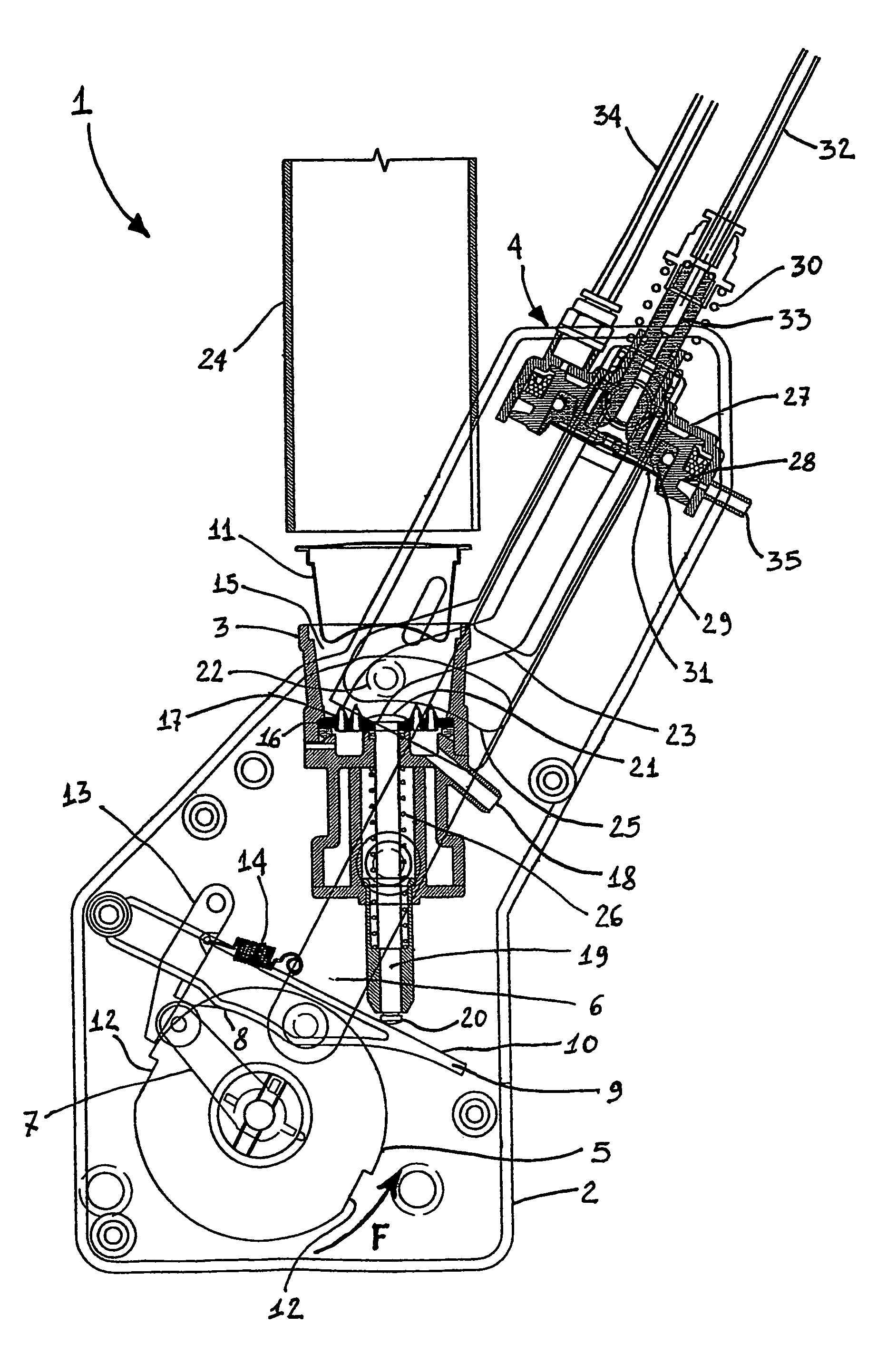
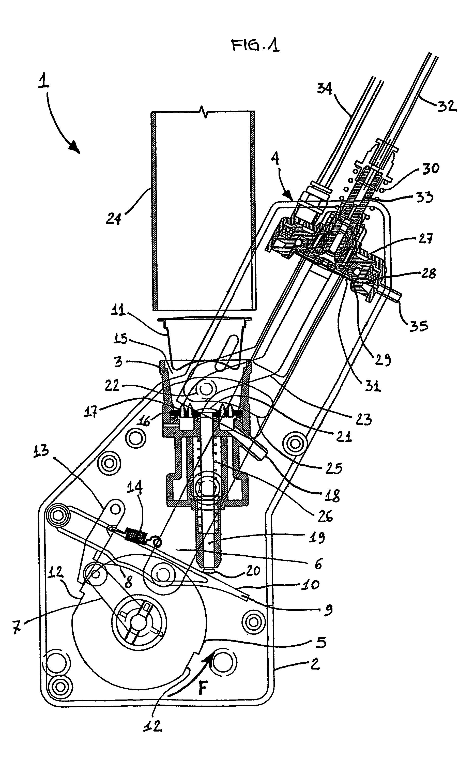
[0014]FIG. 1 illustrates a brewing unit 1 for automatic beverage vending machines, which is constituted by a box-like containment body 2 acting as an outer casing for the entire brewing unit 1, a base 3 and a brewing head 4. Within the box-like containment body 2, in addition to the base 3 and the brewing head 4, there are also housed the mechanical members that form a kinematic chain adapted to operate both the base 3 and the brewing head 4. In particular, these mechanical operating members include a crank 5, to which there is rotatably connected the first end portion of a connecting rod 6, the second end portion of the connecting rod 6 being connected to the brewing unit 4. Firmly joined to the crank 5 there is a cam 7, which interacts with the lower contour 8 of an ejection lever 9 provided with an upper contour 10 that controls the ejection of the capsule 11 from the base 3. In the crank 5 there are provided two recesses 12 adapted to be engaged by a detent lever 13 that is rota...


PUM


Abstract

A mechanically and hydrodynamically operated brewing unit (1) for automatic beverage vending machines includes a rotatable base (3) provided with a compartment (15) that acts as a brewing chamber, means to let water under pressure into said compartment, means to connect said compartment with the point at which the brewed beverage is dispensed, and a brewing head (4). This brewing head is comprised of a hollow containment structure (279), a first hollow piston (28) that is housed in said containment structure movably relative thereto, a second piston (29) that is accommodated in said first piston movably relative thereto, and elastic means (30) contrasting the movement of said second piston. The brewing unit is characterized in that said first piston and said second piston are operated by the direct action of a fluid under pressure.

Description

FIELD OF THE INVENTION[0001]The present invention refers to a mechanically and hydrodynamically operated brewing unit for automatic beverage vending machines, which is adapted to prepare the beverages to be dispensed starting from so-called capsules, preferably hermetically sealed ones, containing the raw material to be brewed.BACKGROUND OF THE INVENTION[0002]In the course of the last few years, there has been a growing use, in automatic vending machines for preparing and dispensing beverages, of so-called capsules, in particular such capsules of a hermetically sealed type, which contain a raw material ready for brewing. These sealed capsules are constituted by semi-rigid envelopes provided with a collet, which create a physical barrier separating their contents from the surrounding ambient. In beverage vending machines, capsules of this kind are certainly by far preferably over both the traditional pre-filled filters, i.e. filters that are filled in advance with the raw material fo...

Claims


Application Information

Patent Timeline
IPC IPC(8): A47J31/40A47J31/36
CPCA47J31/3628A47J31/3633A47J31/3638
Inventor MAGNO, ALESSANDRO
Owner N& W GLOBAL VENDING
Why Eureka
Try Eureka