Method and apparatus for quiet fan speed control

a fan speed control and fan motor technology, applied in the direction of motor/generator/converter stopper, dynamo-electric converter control, starter details, etc., can solve the problems of generating mechanical and annoying and distracting, and producing substantial amounts of acoustic noise in the fan motor

Active Publication Date: 2009-02-10
LUTRON TECH CO LLC
View PDF55 Cites 48 Cited by
  • Summary
  • Abstract
  • Description
  • Claims
  • Application Information

AI Technical Summary

Problems solved by technology

A problem with known techniques for controlling the speed of fan motors is that some of the methods have produced substantial amounts of acoustic noise in the fan motor and the fan speed control, i.e., the control device operating the fan motor. FIG. 1A shows a prior art variable fan speed control 10.
A problem with the prior art fan speed control 10 is that when a fan motor 18 is controlled by the phase angle technique, mechanical and acoustic noises are generated in the fan motor, which can be annoying and distracting. FIG. 1B shows the waveforms of the AC input voltage 19A, the motor voltage 19B applied to the fan motor 18, and the motor current 19C through the fan motor.
The harmonics in the motor voltage 19B delivered to the fan motor 18 causes significant amounts of distracting noise and vibration.
Additional capacitors and switches can be provided to obtain more discrete speed levels, but the circuitry becomes unnecessarily complex, large, and expensive as more components are added.
However, the fan speed control 20 is susceptible to generating noise when the control circuit 26 changes the speed of the fan motor 18, i.e., when the control circuit changes the conduction state of the switches 22, 23.
Repetitive occurrences of such a large current can damage the capacitors and other electrical parts of the fan speed control 20, thereby decreasing the life of the fan speed control.
Further, the discharge resistors 27, 28 dissipate a large amount of power during normal operation of the fan speed control 20, thus requiring rather large and expensive resistors.
Furthermore, the fan motor 18 often has trouble starting up when the fan motor is turned on to a very low speed from off.
However, changing the speed of the fan motor 18 from the initial off speed to the full speed, and then back down to the desired low speed, can generate a large pulse of current through the fan motor, which can cause the fan motor to make an audible “clunking” noise.
As previously mentioned, acoustic noises produced in the fan motor can be annoying and distracting to a user.

Method used


Image

  • Method and apparatus for quiet fan speed control
  • Method and apparatus for quiet fan speed control
  • Method and apparatus for quiet fan speed control

Examples


second embodiment

[0050]In a second alternative method, the voltages across the capacitors 112, 122, 132 are monitored to determine when to turn off the switches 110, 120, 130. FIG. 6A is a simplified schematic diagram of a quiet fan speed control 300 according to the present invention. The fan speed control 300 includes a voltage compare circuit 350, which is operable to receive the voltages across each of the capacitors 112, 122, 132. FIG. 6B is a simplified schematic diagram of a possible implementation of the voltage compare circuit 350. The voltage compare circuit 350 comprises three comparator circuits 360, 370, 380 for comparing each of the voltages across the capacitors 112, 122, 132 to a reference voltage VREF1, VREF2, VREF3, respectively. The first comparator circuit 360 includes a comparator 362 with the reference voltage VREF1 connected to the negative input. The voltage across the capacitor 112, 122, 132 is received through a diode 364 during the positive half-cycles of the motor current...

third embodiment

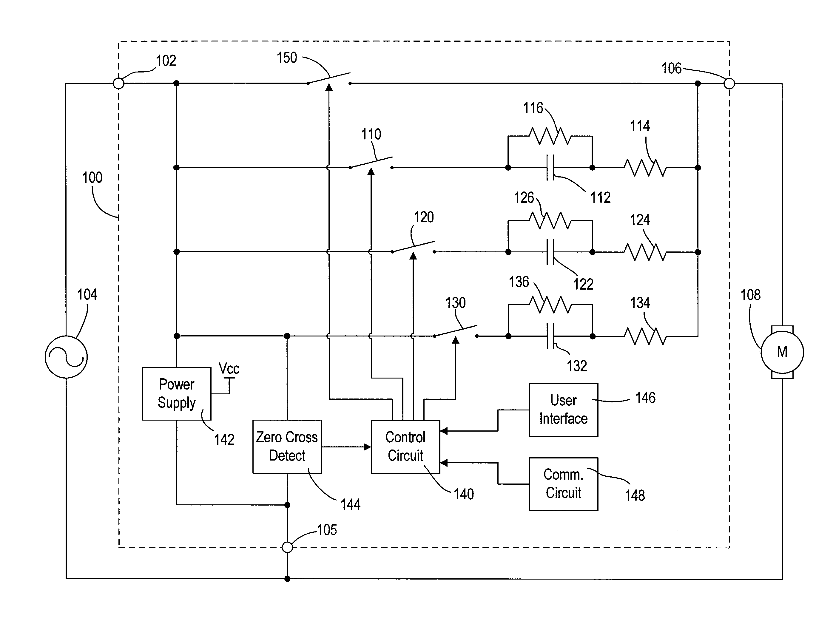
[0051]In a final alternative embodiment, the control circuit 140 is operable to monitor the motor current IM through the fan motor 108 in order to control the switches 110, 120, 130. FIG. 6C is a simplified schematic diagram of a quiet fan speed control 400 according to the present invention. The fan speed control 400 includes a voltage monitor circuit 490, which provides to the control circuit 140 a signal representative of the zero-crossings of the voltage across the limiting resistors 116, 126, 136, and thus the zero-crossings of the motor current IM. Accordingly, the control circuit 140 is operable to turn off the switches 110, 120, 130 at the zero-crossings of the motor current IM.

[0052]To start up the fan motor 108 from off to a substantially low speed (e.g., speed #1 or speed #2 of Table 1) without generating excessive acoustic noise in the fan motor, the fan speed control 100 of the present invention first turns on the fan motor to an intermediate speed, i.e., not the maximu...


PUM


Abstract

An AC motor speed controller includes a plurality of capacitors that may be selectively switched, by means of controllably conductive switches, into series electrical connection with an AC motor and an AC voltage source to control the speed of the motor. To change the speed of the motor, a control circuit renders a first switch conductive, in response to a first detected AC voltage zero crossing, to charge a first capacitor to a predetermined voltage. The control circuit then renders a second switch conductive, in response to a subsequent second detected AC voltage zero crossing, to charge a second capacitor to the predetermined voltage. The control circuit then renders both switches simultaneously conductive at a predetermined time after a subsequent third detected AC voltage zero crossing. The capacitors will thereby be charged to the same voltage prior to being switched into series with the motor, thereby resulting in reduced acoustic noise when changing motor speeds.

Description

RELATED APPLICATIONS[0001]This application claims priority from commonly-assigned U.S. Provisional Patent Application Ser. No. 60 / 738,017, filed Nov. 18, 2005, having the same title as the present invention, the entire disclosure of which is hereby incorporated by reference.BACKGROUND OF THE INVENTION[0002]1. Field of the Invention[0003]The present invention relates to load control devices for providing variable power to alternating-current (AC) loads, for example, motor loads, such as AC fan motors. More particularly, the invention relates to quiet fan speed control, specifically for controlling of the speed of a ceiling-mounted cooling fan quickly while minimizing the generation of acoustic noise.[0004]2. Description of the Related Art[0005]A problem with known techniques for controlling the speed of fan motors is that some of the methods have produced substantial amounts of acoustic noise in the fan motor and the fan speed control, i.e., the control device operating the fan motor...

Claims


Application Information

Patent Timeline
Patent Type & Authority Patents(United States)
IPC IPC(8): H02P7/06
CPCH02P1/24H02P7/288Y02B30/70
Inventor STEINER, JAMES P.DOBBINS, AARONWU, CHEN MING
Owner LUTRON TECH CO LLC
Why Eureka
Try Eureka