Electromagnetic field generating element, information recording/reproducing head, and information recording/reproducing apparatus

a technology generating element, which is applied in the field of information recording/reproducing head, information recording/reproducing apparatus, and information recording/reproducing element. it can solve the problems of slow response, low frequency, and inability to carry out good thermally assisted magnetic recording/reproduction, and achieve the effect of simple structur

Inactive Publication Date: 2009-02-10
SHARP KK
View PDF24 Cites 10 Cited by
  • Summary
  • Abstract
  • Description
  • Claims
  • Application Information

AI Technical Summary

Benefits of technology

[0017]The light irradiation means irradiates light by (i) oscillating light or (ii) changing orientation of light irradiated from an external apparatus to the light irradiation means. The light irradiation means irradiates the light, to the conductor having the plate-like shape, light substantially parallel to the extending flat surface of the conductor. This causes generation of a near field in the surface of the conductor. The near field thus generated is propagated via the surface of the conductor, in the light irradiation direction. When the near field is propagated to an edge portion of the conductor, the orientation of the near field is dramatically changed along the surface of the conductor. Accordingly, an electric field is concentrated in the edge portion of the conductor. This causes generation of a strong localized near field from the edge portion of the conductor. As such, generated in the edge portion of the conductor are: (i) the near field generated by the light irradiation, and (ii) the localized near field generated in the direction in which the propagated near field travels. Therefore, such a stronger near field can be generated in the vicinity of the edge portion of the conductor. In this way, the structure above makes it possible to generate the near field in the vicinity of the edge portion of the conductor.
[0018]Further, the supply of the current to the conductor generating the near field allows generation of a magnetic field in the vicinity of the conductor. Generally, the magnetic field is stronger as distance is shorter to the portion in which the magnetic field is generated. For this reason, the magnetic field generated in the vicinity of the conductor is strong. As such, the structure above makes it possible to generate both the near field and the magnetic field in the vicinity of the edge portion of the conductor. In other words, the structure does not use a yoke extension section etc., for inducing the magnetic field; however, the structure makes it possible to generate the strong magnetic field directly in the region in which the near field is generated. Therefore, the structure above allows realization of an electromagnetic field generating element that allows restraint of the magnetic field attenuation and the magnetic field delay.
[0021]Therefore, for generation of a strong magnetic field in a desired location, the confinement portion obtained by narrowing a portion of the conductor is formed in the location. That is, the electromagnetic field generating element does not need to use the yoke extension section so as to generate the magnetic field in such a desired location, so that the electromagnetic field generating element allows restraint of magnetic field attenuation or magnetic field delay as compared with the case of using the yoke extension section. This makes it possible to provide an electromagnetic field generating element suitable for the high frequency magnetic recording / reproduction.
[0022]In addition, the magnetic field is generated by supplying a current to the conductor. Further, the light irradiated from the light source is propagated to the conductor having the confinement portion, with the result that the light is irradiated to the conductor having the confinement portion. The light irradiation causes excitation of plasmon in the interface between (i) the conductor having the confinement portion and (ii) the substrate. This causes generation of the near field. The near field thus generated is propagated, via the side surface of the conductor, to the bank-like structure formed along the edge portion of the confinement portion of the conductor. In the bank-like structure, the near field is strengthened. This allows restraint of variation in strength distribution of the near field.
[0023]As such, the structure above generates the magnetic field and the near field in the confinement portion. In other words, the structure above makes it possible to generate the magnetic field and the near field in substantially the same location. Further, the magnetic field and the near field can be generated in a desired location by changing the position, of the confinement portion of the conductor which has a simple structure and which is provided in the substrate.

Problems solved by technology

However, the conventional structures suffer from such a problem that good thermally assisted magnetic recording / reproduction cannot be carried out, at a high frequency, with respect to the minute region in the medium.
The strength attenuation of the magnetic field gives rise to decrease of output for the writing, whereas the propagation delay thereof gives rise to slow responsiveness.
For this reason, the flying recording head having such a structure is not suitable for the high frequency magnetic recording / reproduction.
For this reason, the techniques are not suitable for the near field assisted recording which requires the near field for the recording onto a minute region of the medium.

Method used


Image

  • Electromagnetic field generating element, information recording/reproducing head, and information recording/reproducing apparatus
  • Electromagnetic field generating element, information recording/reproducing head, and information recording/reproducing apparatus
  • Electromagnetic field generating element, information recording/reproducing head, and information recording/reproducing apparatus

Examples


embodiment 1

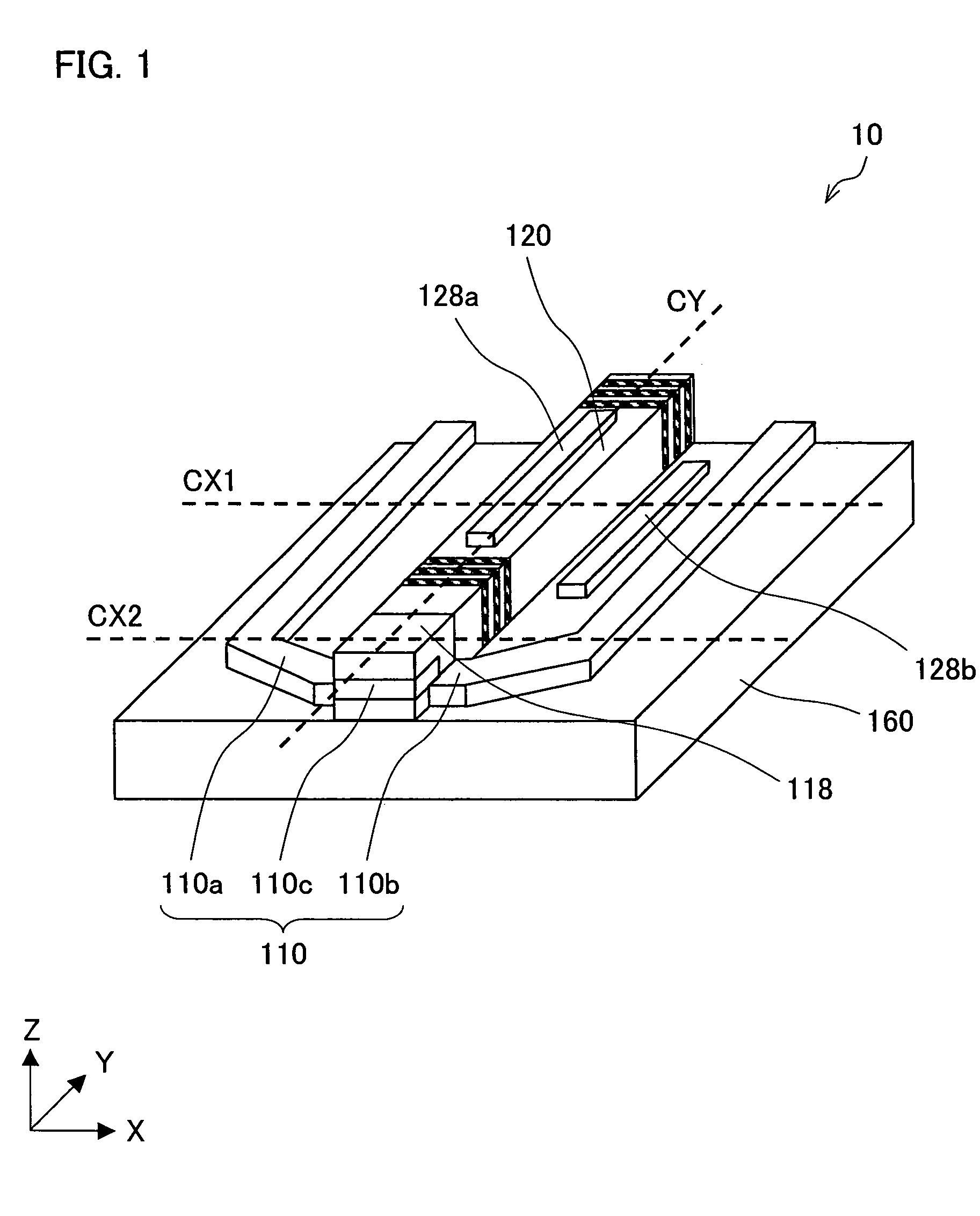
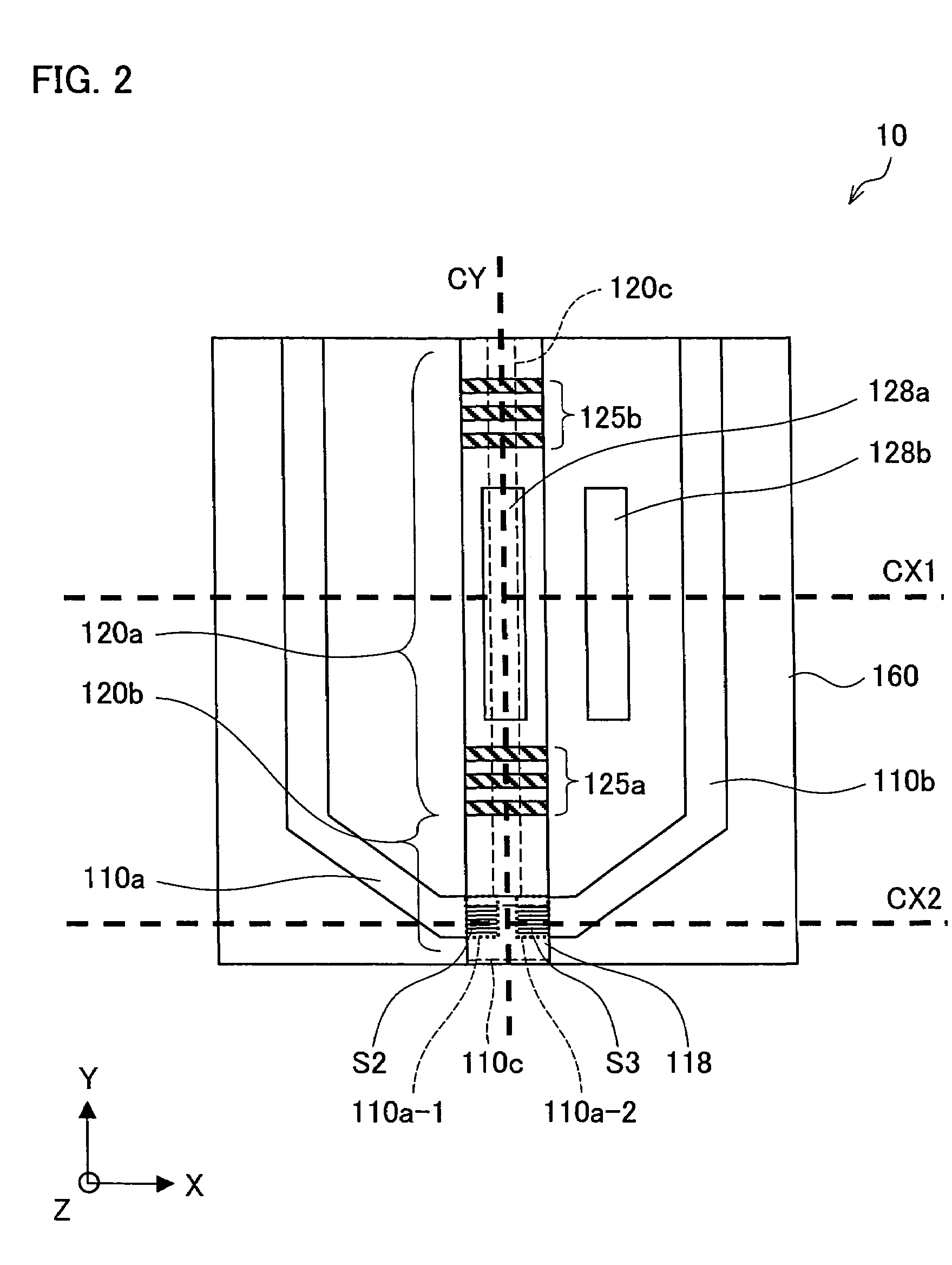
[0102]The following explains one embodiment of an electromagnetic field generating element according to the present invention, with reference to FIG. 1 through FIG. 7.

[0103]FIG. 1 is a diagram schematically illustrating the electromagnetic field generating element 10 according to the present embodiment. The electromagnetic field generating element 10 includes (i) a substrate 160, (ii) a semiconductor laser element 120 provided on the substrate 160, and (iii) a conductor clump 110.

[0104]Here, see the following definitions given for the sake of the clarity of explanation: (i) defined as “XY flat surface” is a surface whose sides respectively extending along the sides of the substrate 160; (ii) defined as “Z axis” is line perpendicular to the substrate 160; (iii) defined as “Z axis positive direction” is the upward direction of the substrate 160; (iv) defined as “Y axis direction” is the resonance direction of the semiconductor laser element 120 having a rectangular solid shape; (v) de...

embodiment 2

[0153]The following explains another embodiment of the electromagnetic generating element according to the present invention, with reference to FIG. 8 through FIG. 12. Note that materials having the equivalent functions as those shown in the drawings pertaining to the foregoing Embodiment 1 will be given the same reference symbols, and explanation thereof will be omitted here.

[0154]FIG. 8 is a diagram schematically illustrating an electromagnetic field generating element 20 of the present embodiment. In the electromagnetic field generating element 20 of the present embodiment, a semiconductor laser element 120 and a conductor clump 110 are provided on a substrate 160. The conductor clump 110 is made up of conductors 110d, 110e, and 110f, each of which is in the form of a plate. The conductors 110d, 110e, and 110f are provided such that their film surfaces are each substantially parallel to the resonance direction of the semiconductor laser 120. The conductor 110f serves as a confine...

embodiment 3

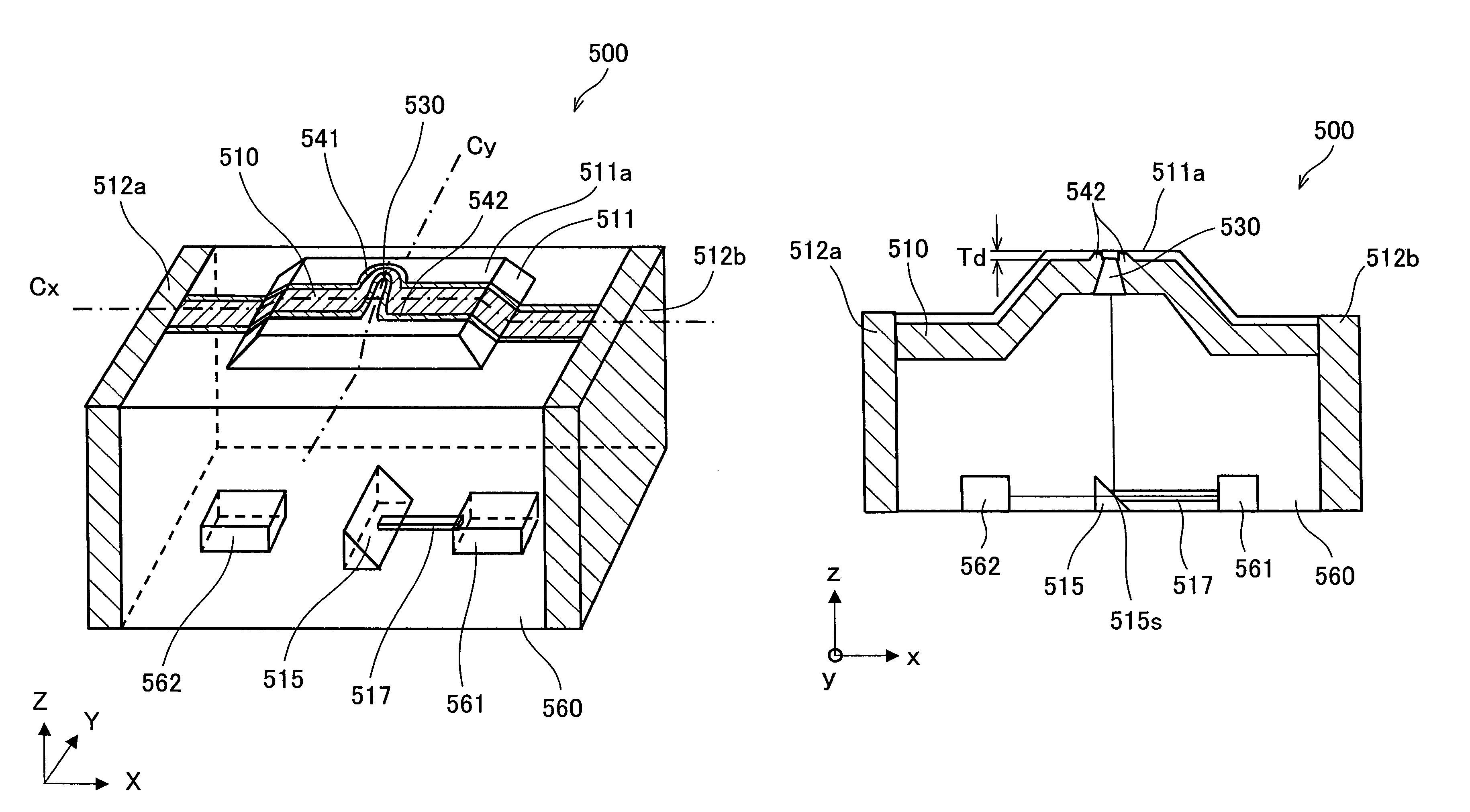
[0181]The following explains one embodiment of an information recording / reproducing head according to the present invention, with reference to FIG. 15 through FIG. 19. Note that materials having the equivalent functions as those shown in the drawings pertaining to the foregoing embodiments will be given the same reference symbols, and explanation thereof will be omitted here.

[0182]Explained in the present embodiment is an information recording / reproducing head obtained by providing a light detector 163 in the electromagnetic field generating element 10 described in Embodiment 1. The light detector 163 serves as an electromagnetic field detector.

[0183]FIG. 16 is a cross sectional view schematically illustrating such an information recording / reproducing head 30 of the present embodiment.

[0184]In the information recording / reproducing head 30 of the present embodiment, a soft magnetic layer 119 is provided on the insulating layer 118 of the electromagnetic field generating element 10. F...


PUM

PropertyMeasurementUnit
angleaaaaaaaaaa
height Ahaaaaaaaaaa
height Ahaaaaaaaaaa

Abstract

An electromagnetic field generating element restrains magnetic field attenuation or magnetic field delay in a high frequency recording / reproducing head for thermally assisted magnetic field recording / reproduction using a near field. An information recording / reproducing head and an information recording / reproducing apparatus carry out high frequency magnetic recording / reproduction. The electromagnetic field generating element includes: (i) a substrate, (ii) conductors each provided on the substrate and each serving as a supporting section, (iii) a plate-like-shaped conductor provided on the conductors and (iv) a semiconductor laser element provided on the substrate. The semiconductor laser element irradiates laser light to the plate-like-shaped conductor substantially parallel to an extending flat surface of the plate-like-shaped conductor. This causes generation of a near field in the plate-like-shaped conductor. In addition, a magnetic field is generated by supplying a current to the plate-like-shaped conductor.

Description

[0001]This Nonprovisional application claims priority under 35 U.S.C. § 119(a) on (i) Patent Application No. 2004 / 298735 filed in Japan on Oct. 13, 2004, (ii) Patent Application No. 2004 / 280670 flied in Japan on Sep. 27, 2004, and (iii) Patent Application No. 2005 / 031149 filed in Japan on Feb. 7, 2005, the entire contents of which are hereby incorporated by reference.FIELD OF THE INVENTION[0002]The present invention relates to an electromagnetic field generating element, an information recording / reproducing head, and an information recording / reproducing apparatus. Specifically, the present invention relates to (i) an electromagnetic field generating element for generating a near field and a magnetic field, (ii) an information recording / reproducing head including the electromagnetic field generating element, or (iii) an information recording / reproducing apparatus including the electromagnetic field generating element.[0003]Note that the wording “information recording / reproducing appa...

Claims


Application Information

Patent Timeline
Patent Type & Authority Patents(United States)
IPC IPC(8): G11B11/24G11B11/00
CPCG11B5/1278G11B5/314G11B7/1387G11B11/10536G11B11/10541G11B11/1058G11B2005/0002G11B2005/0021
Inventor MIYANISHI, SHINTAROIKETANI, NAOYASUKOJIMA, KUNIO
Owner SHARP KK
Why Eureka
Try Eureka