
Decision feedback equalizer and precoder ramping circuit

Inactive Publication Date: 2009-02-10
AVAGO TECH INT SALES PTE LTD
View PDF21 Cites 4 Cited by
  • Summary
  • Abstract
  • Description
  • Claims
  • Application Information

AI Technical Summary

Benefits of technology

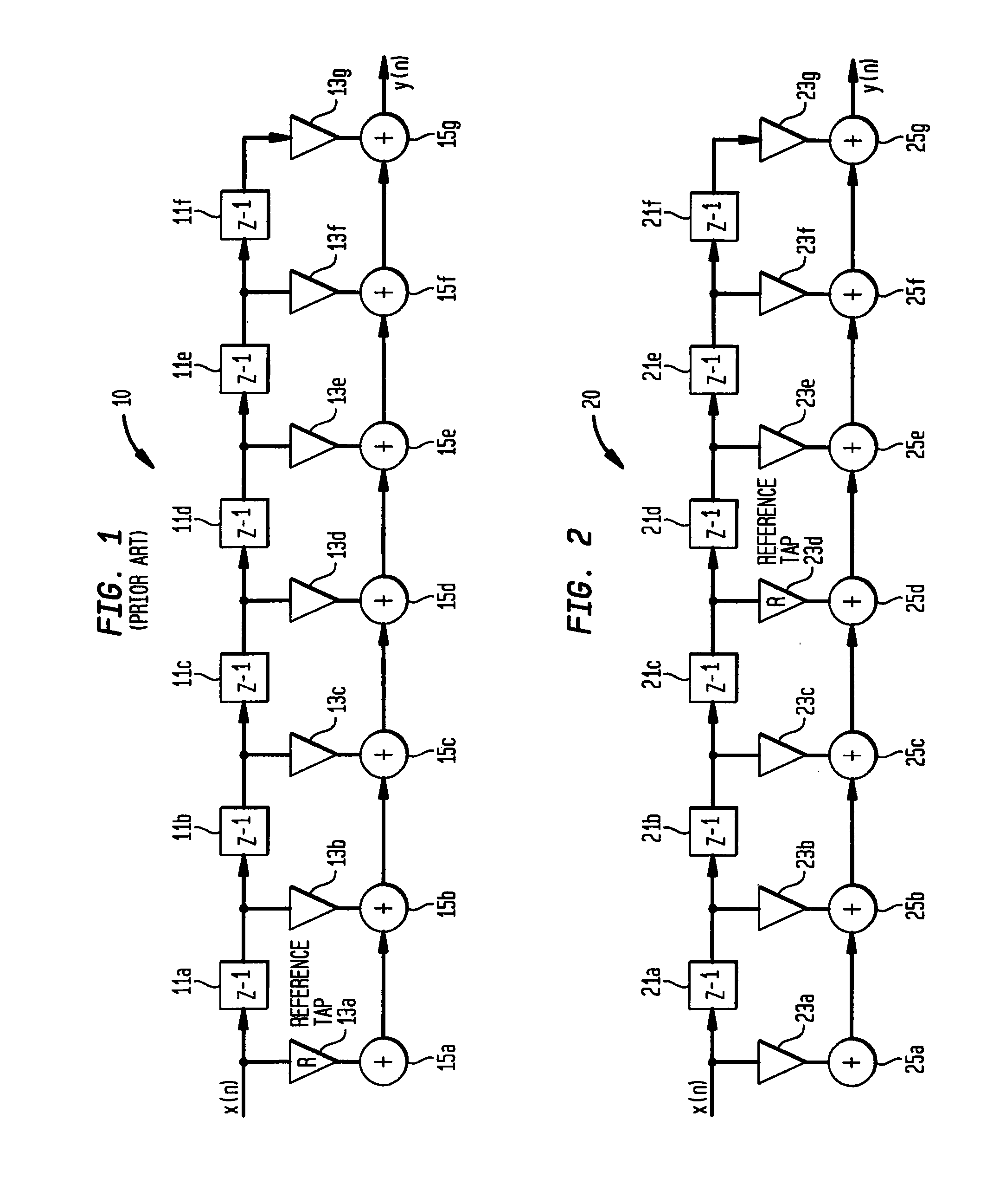
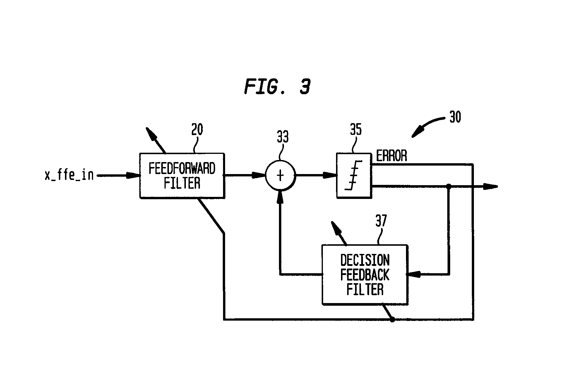
[0031]Thus, a receiver for a DSL communication system or like includes a feedforward filter coupled to process signals received by the receiver. The feedforward filter has a plurality of feedforward filter taps, including a feedforward filter reference tap. A feedback filter is coupled to receive signals representative of an output of the feedforward filter. The feedback filter has a plurality of feedback filter taps. The feedforward filter reference tap is located proximate a center position of the feedforward filter, so as to enhance noise cancellation in a DSL communication system or the like.
[0032]According to one aspect of the present invention, a transceiver is defined which includes a transmitter and a receiver. The receiver includes a feedforward filter coupled to process signals received by the receiver. The feedforward filter has a plurality of feedforward filter taps, including a feedforward filter reference tap. A feedback filter is coupled to receive signals representative of an output of the feedforward filter. The feedback filter has a plurality of feedback filter taps. The feedforward filter reference tap is located proximate a center position of the feedforward filter, so as to enhance noise cancellation in a DSL communication system or the like.
[0033]According to another aspect of the present invention, a communication system includes a plurality of transceivers, at least two of which are configured to communicate with one another. Each transceiver includes a transmitter and a receiver. Each receiver includes a feedforward filter coupled to process signals received by the receiver, the feedforward filter has a plurality of feedforward filter taps, including a feedforward filter reference tap. A feedback filter is coupled to receive signals representative of an output of the feedforward filter. The feedback filter has a plurality of feedforward filter taps. The feedforward filter reference tap is located proximate a center position of the feedforward filter, so as to enhance noise cancellation in a DSL communication system or the like.
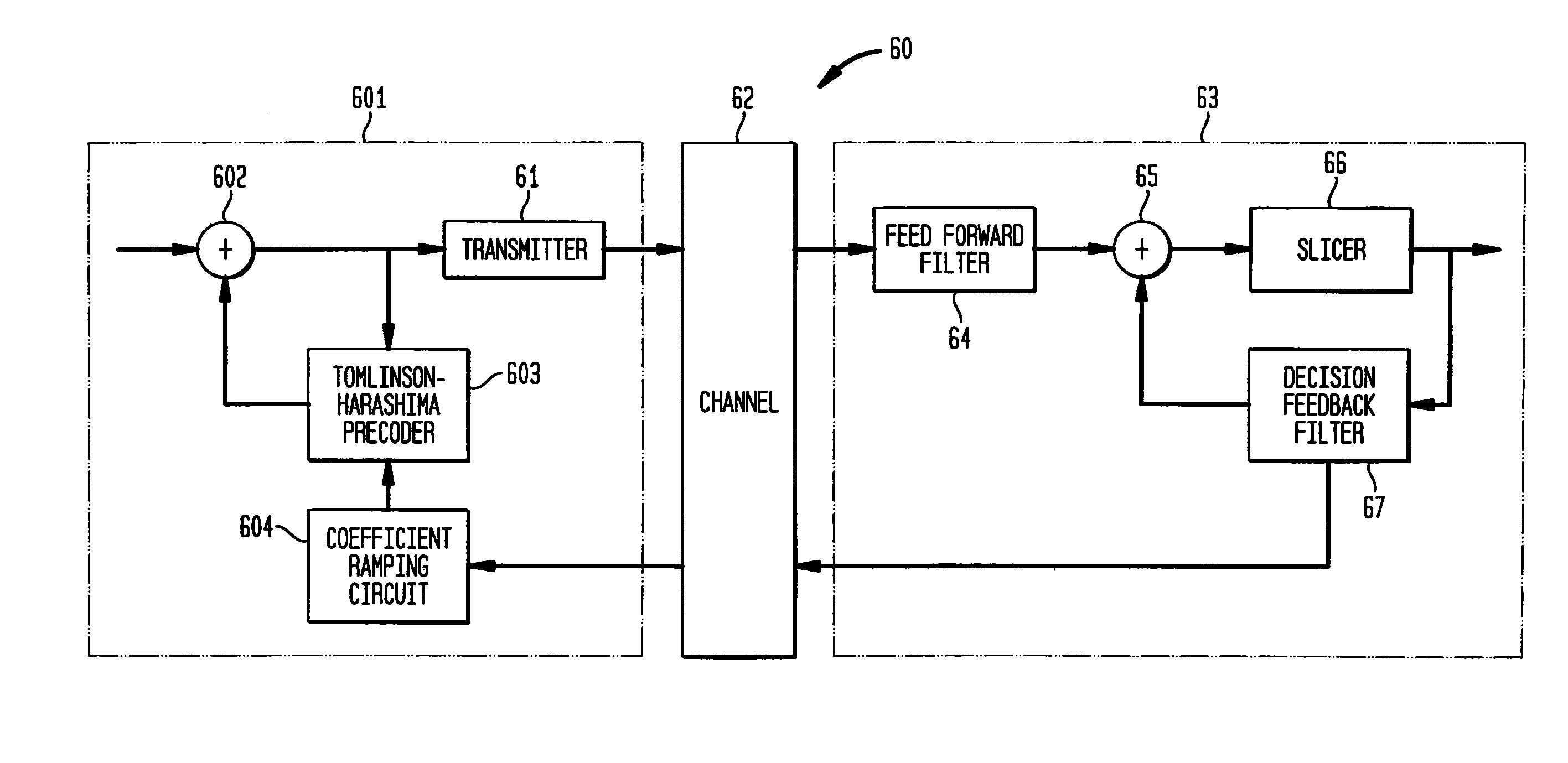
[0035]According to another aspect, the present invention includes a ramping circuit for facilitating inhibition of the undesirable effects of intersymbol interference (ISI). The ramping circuit includes an input port configured to receive at least one decision feedback filter tap coefficient from a decision feedback filter and a coefficient ramping circuit configured to provide a ramped output for at least one of the decision feedback filter tap coefficients, wherein the ramped output is ramped over time from a first value to second value. The second value is dependent upon a decision feedback filter tap coefficient. An output port of the ramping circuit is configured to communicate information representative of the ramped output(s) to a precoder. According to one aspect, the present invention includes a receiver having a decision feedback filter and a ramping circuit assembly. The ramping circuit assembly includes an input port configured to receive at least one decision feedback filter tap coefficient from the decision feedback filter. A coefficient ramping circuit is configured to provide a ramped output for at least one of the decision feedback filter tap coefficients. The ramped output is ramped over time from a first value to a second value, wherein the second value is dependent upon a decision feedback filter tap coefficient. An output port of the ramping circuit assembly is configured to communicate information representative of the ramped output(s) to a precoder of a remotely located transmitter.

Problems solved by technology

Due to the increasingly large quantity of digital data being communication via twisted pair telephone lines, the maximum bit rate associated with voiceband modems is frequently considered inadequate.
The comparatively slow speed of voiceband modems is a severe limitation when transferring large binary files such as images, film clips, audio, large data files and the like.
At 56 Kbps, such files may require an undesirably long amount of time to transfer between computers.
Further, many applications, such as those involving realtime video, are not possible at 56 Kbps.
Even the comparatively high speed associated with ISDN is not adequate for providing such services, which typically require data rates of at least 1.5 Gbps.
It is worthwhile to note that although fiber optic cable will provide data rates in excess of those possible utilizing DSL on twisted pair telephone lines, the installation of fiber optic cable to customer premises is costly and is expected to take more than a decade.
However, this high bit rate is in the downstream direction only.
One major problem which inhibits optimization of the bit rate in DSL installations is radio frequency ingress (RFI).
Leakage of some portion of the RFI past the differential amplifiers inherently occurs since it is not possible to define a twisted pair transmission medium which is completely balanced.
Thus, such differential mode induced RFI undesirably interferes with the received signal and thereby degrades the performance of the DSL system, resulting in an undesirably reduced bit rate.
Another problem associated with DSL installations which inhibits optimization of bit rate is intersymbol interference (ISI).
As those skilled in the art will appreciate, when the post-cursor ISI of one symbol, for example, extends into a subsequent symbol, this post-cursor ISI increases the amplitude of the subsequent symbol, thereby potentially causing the subsequent to be misinterpreted by the slicer of the receiver.
ISI becomes much more detrimental as bit rates increase.
Therefore, ISI tends to substantially inhibit optimization of bit rate.

Method used


Image

  • Decision feedback equalizer and precoder ramping circuit
  • Decision feedback equalizer and precoder ramping circuit
  • Decision feedback equalizer and precoder ramping circuit

Examples


Embodiment Construction

[0052]The detailed description set forth below in connection with the appended drawings is intended as a description of the present embodiments of the invention and is not intended to represent the only forms in which the present invention may be constructed or utilized. The description sets forth the functions of the invention and the sequence of steps for constructing and operating the invention in connection with the illustrated embodiments. It is to be understood, however, that the same or equivalent functions and sequences may be accomplished by different embodiments that are also intended to be encompassed within the spirit and scope of the invention.

[0053]Although the present invention is described and illustrated herein as being implemented—in a digital subscriber line (DSL) system, such is by way of example and not by way of limitation. As those skilled in the art will appreciate, the present invention is suitable for application in a variety of different types of communica...


PUM


Abstract

A feedforward filter has a plurality of feedforward filter taps, including a feedforward filter reference tap. The reference tap of the feedforward filter is positioned proximate a center position of the feedforward filter. A ramping circuit assembly has an input port configured to receive at least one decision feedback filter tap coefficient from a decision feedback filter. A coefficient ramping circuit is configured to provide a ramped output for at least one of the decision feedback filter tap coefficients. The ramped output is varied over time from a first value to a second value. The second value is dependent upon the value of a decision feedback filter tap coefficient. An output port of the ramping circuit assembly is configured to communicate information representative of the ramped output(s) to a precoder.

Description

CROSS REFERENCE TO RELATED APPLICATIONS[0001]The present application is a continuation of patent application Ser. No. 09 / 619,125, filed Jul. 18, 2000 now abandoned, which is a divisional of patent application Ser. No. 09 / 550,757, filed Apr. 17, 2000 now abandoned, which claims the benefit of U.S. Provisional Patent Application Ser. Nos. 60 / 148,978, filed Aug. 13, 1999, and entitled DSL ADAPTIVE TOMLINSON ALGORITHMS and 60 / 148,801, filed Aug. 13, 1999, and entitled DSL EQUALIZER. All these applications are expressly incorporated herein by referenced as though fully set forth in full.FIELD OF THE INVENTION[0002]The present invention relates generally to electronic communications systems. The present invention relates more particularly to an apparatus and method for enhancing digital communications, such as those taking place via twisted pair telephone lines in digital subscriber line (DSL) systems.BACKGROUND OF THE INVENTION[0003]Voiceband modems for providing digital communications b...

Claims


Application Information

Patent Timeline
IPC IPC(8): H03K5/159H03H21/00H04L25/03
CPCH03H21/0012H04L25/03343H04L25/03993H04L25/4975H04L2025/0349H04L2025/03808
Inventor JAFFE, STEVEN T.JOSHI, ROBINDRAJONES, DAVIDLIN, THUJI SIMON
Owner AVAGO TECH INT SALES PTE LTD
Learn More