
Time of flight teat location system

a technology of time flight and teat, which is applied in the field of automatic detection of the location of animal teats, can solve the problems of significant problems, affecting the quality of images obtained, and affecting the quality of images,

Inactive Publication Date: 2009-02-17
LMI TECH
View PDF23 Cites 59 Cited by
  • Summary
  • Abstract
  • Description
  • Claims
  • Application Information

AI Technical Summary

Benefits of technology

"The invention is a system and method for automatically milking a live animal's teats using a light source and a two-dimensional array camera that can capture the location of the teats in three dimensions. This technology is compact, light, and not limited by depth of field or obstruction. The system includes movable apparatus that can receive instructions on the location of a specific teat and engage it for milking. The light source illuminates the area around the teats, and the camera captures images that are processed to provide the necessary information for the apparatus to engage the teat. The technical effects of this invention include improved efficiency and accuracy in milking, reduced labor costs, and improved animal welfare."

Problems solved by technology

Given the size of the sensor housing, this provides a limited range of movement, which imposes a constraint on the quality of the images that can be obtained, particularly when one teat obstructs another.
This is a significant problem.
Moreover, either of the field of view or the projected light might be obstructed.
In addition to needing to obtain an unobstructed view of the various teats, when several teats are at both different distances and different angles from the sensor, inaccuracies may also arise in assessing the location of the teats by triangulation.
This results in unreliable determination of the absolute location and orientation of the teats.
However that approach is of limited usefulness due to the limited depth of field of current optical triangulation systems.
Stereo imaging systems also face similar problems.
Both cameras must image the same teat at the same time but the use of two cameras increases the risk of a teat being obscured by another at one of the cameras.
The footprint of the sound waves drastically limits spatial resolution.
In addition, the speed of sound is influenced by air temperature and humidity and airflow speeds, and echoing adds noise which must be accommodated in the processing of the image.

Method used


Image

  • Time of flight teat location system
  • Time of flight teat location system
  • Time of flight teat location system

Examples


Embodiment Construction

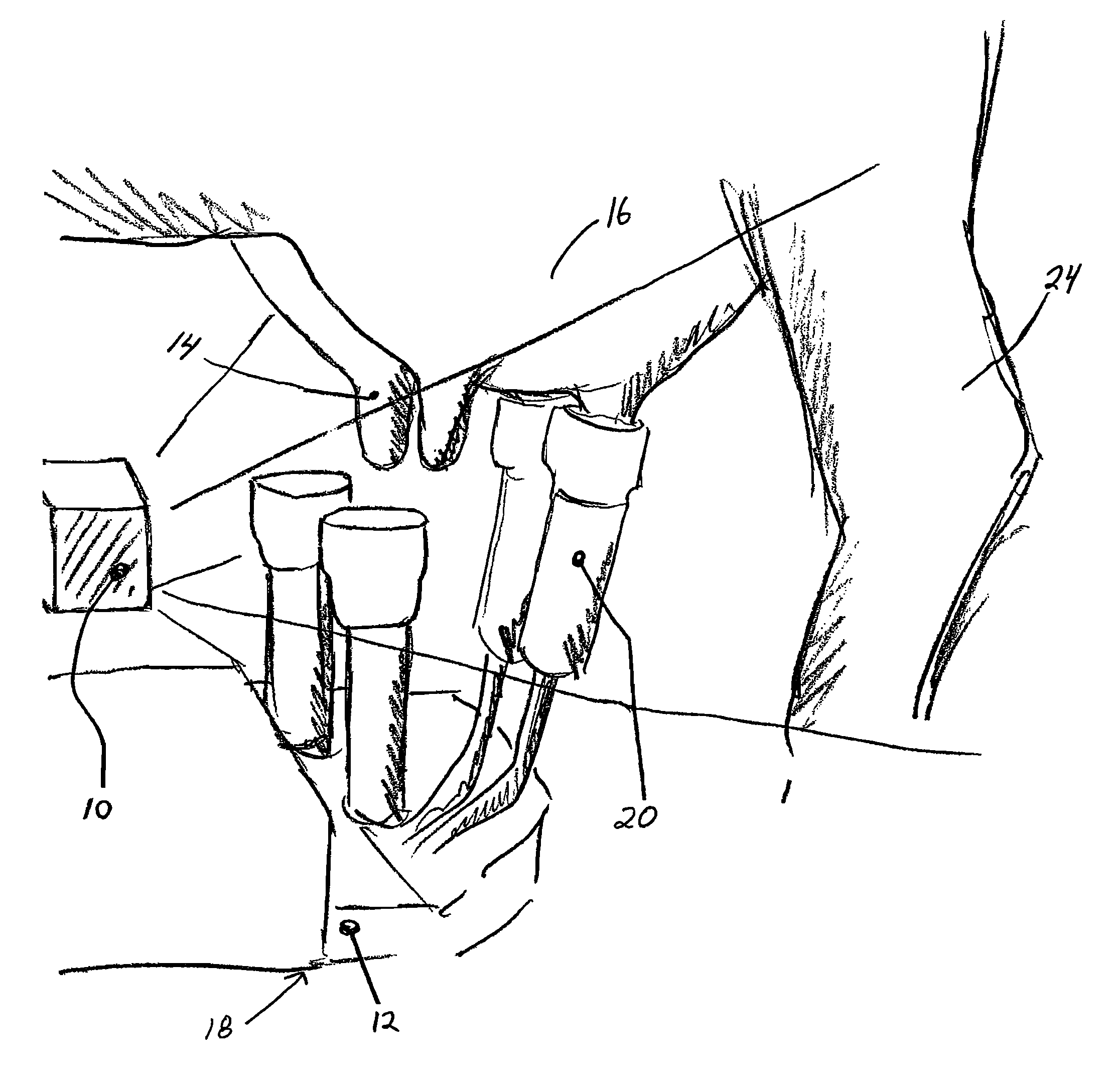
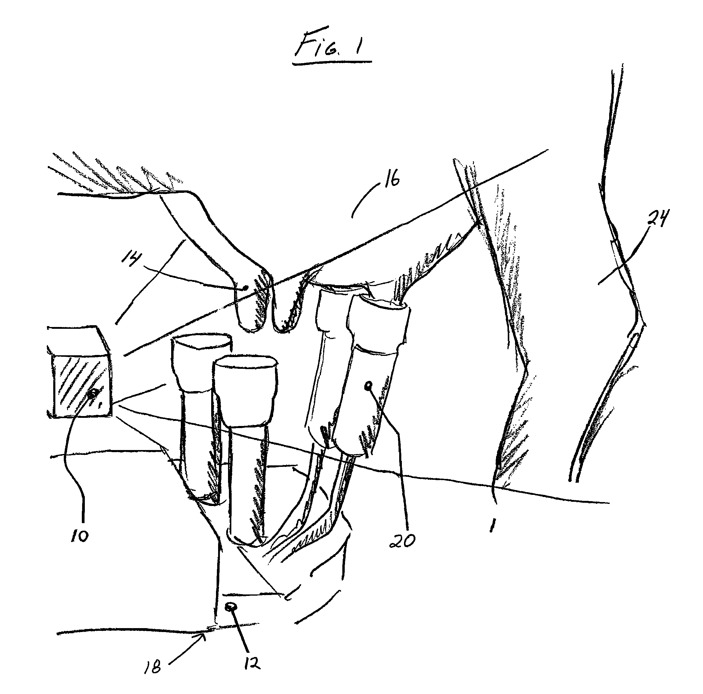
[0023]FIG. 1 illustrates the preferred embodiment of the invention. A sensor housing 10 is mounted on robot arm 12 for sensing the location and attitude of teats 14 on an udder 16. The output of the sensor is used to control the application of the automated milking apparatus 18 that includes milking cups 20 that are also mounted on robot arm 12. The milking apparatus is adapted to receive instructions characterizing the location of the teats, to move the robot arm to such location so as to engage the milking cups onto the teats.

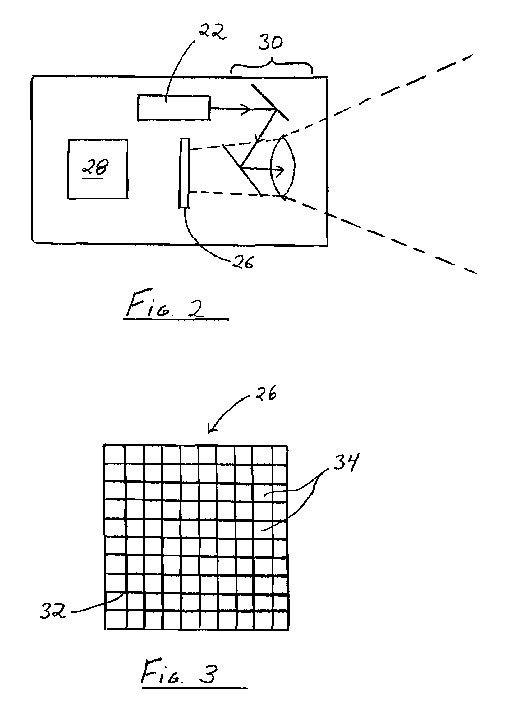
[0024]Sensor housing 10 includes a modulated light source 22 for radiating throughout the field of view that encompasses the udder 16, the teats 14 and the hind legs 24 of the animal. Referring to FIG. 2, sensor housing 10 includes a camera 26, control, image capture and readout electronics 28 and suitable optics 30.

[0025]As illustrated schematically in FIG. 3, camera 26 consists of a two-dimensional array 32 of pixels 34, each of which can report time of fli...


PUM


Abstract

A teat location system for automated milking systems comprises a light projection source and a camera having a two dimensional array of pixels, each of which is capable of returning time of flight information as well as intensity. Depth of field limitations and the problem of overlapping teat images are thereby overcome or minimized.

Description

CROSS REFERENCES TO RELATED APPLICATIONS[0001]This Application claims priority to Canadian patent application serial no.: 2,539,645, filed Mar. 15, 2006, all of which is herein incorporated in its entirety by this reference thereto.FIELD OF THE INVENTION[0002]This invention relates to the automated detection of the location of animal teats for the purpose of controlling automated milking apparatus.BACKGROUND OF THE INVENTION[0003]It is known in the field of automated milking to use optical sensors to determine the attitude and location in three dimensions of the teats in order to guide the milking apparatus. Laser-based optical triangulation sensors are used to image the teats and to derive their position in three dimensions. Light is projected into the field of view and the reflected light is imaged on a camera that lies in the projection plane. The optics as well as the light source are housed in a sensor enclosure, the size of which must accommodate the optics involved.[0004]The ...

Claims


Application Information

Patent Timeline
Patent Type & Authority Patents(United States)
IPC IPC(8): A01J5/00A01J5/017
CPCA01J5/0175
Inventor METCALFE, LEONARDMAAS
Owner LMI TECH
Learn More