Back rest for a chair

a backrest and chair technology, applied in the field of backrests for chairs, can solve the problems of back falling off from the back support, and achieve the effects of compact construction, reduced weight, and reduced weigh

Inactive Publication Date: 2009-02-17
SEDUS STOLL
View PDF9 Cites 9 Cited by
  • Summary
  • Abstract
  • Description
  • Claims
  • Application Information

AI Technical Summary

Benefits of technology

[0010]A simple configuration of the joint results when at least one of the two elastic elements is ring-shaped and the back surface is joined to the joint plate through this ring-shaped elastic element.
[0011]For the two elastic elements, a compressible foam material is preferably used, especially an open-pore PUR foam material. In this case, the elastic elements can be dimensioned such that they, along with the joint plate, entirely fill up the inner space of the receiving chamber and therefore the joint is free of play. The two elastic elements are even preferably precompressed in the receiving chamber so as to achieve greater stiffness of the joint. This also produces an advantageously small volume for the receiving chamber, so that the joint as a whole can be very compact in construction. This would not be possible with an elastic rubber material, as used in the prior art, because although an elastic rubber material is elastically deformable, it is hardly compressible at all, and therefore free space would have to be provided in the receiving chamber.

Problems solved by technology

The drawback to this design is that the back falls away from the back support when the connection between one of the end plates and the elastic rubber element is released.
If this occurs when a person is leaning against the back rest, the person can fall backward resulting in serious injuries.

Method used


Image

  • Back rest for a chair
  • Back rest for a chair
  • Back rest for a chair

Examples


Embodiment Construction

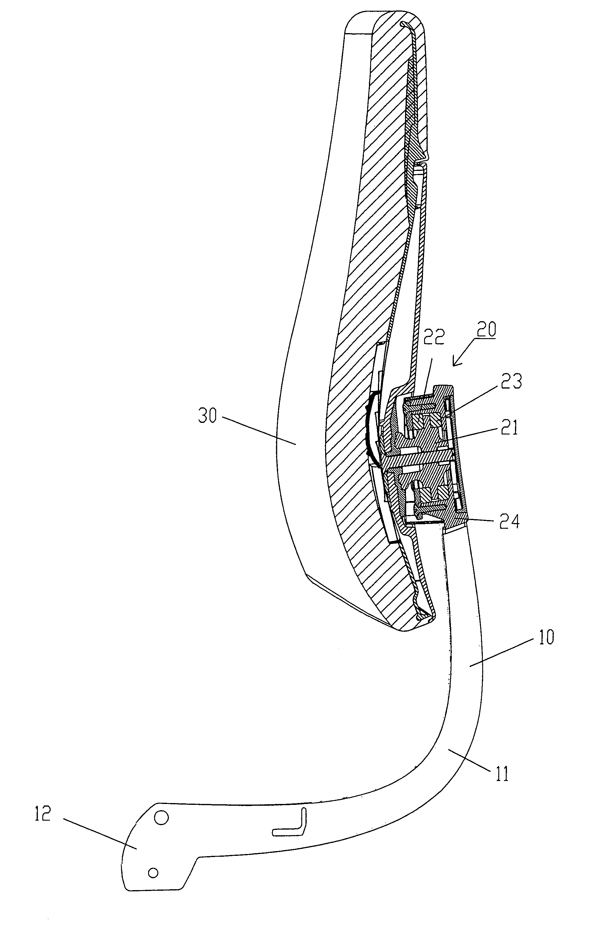
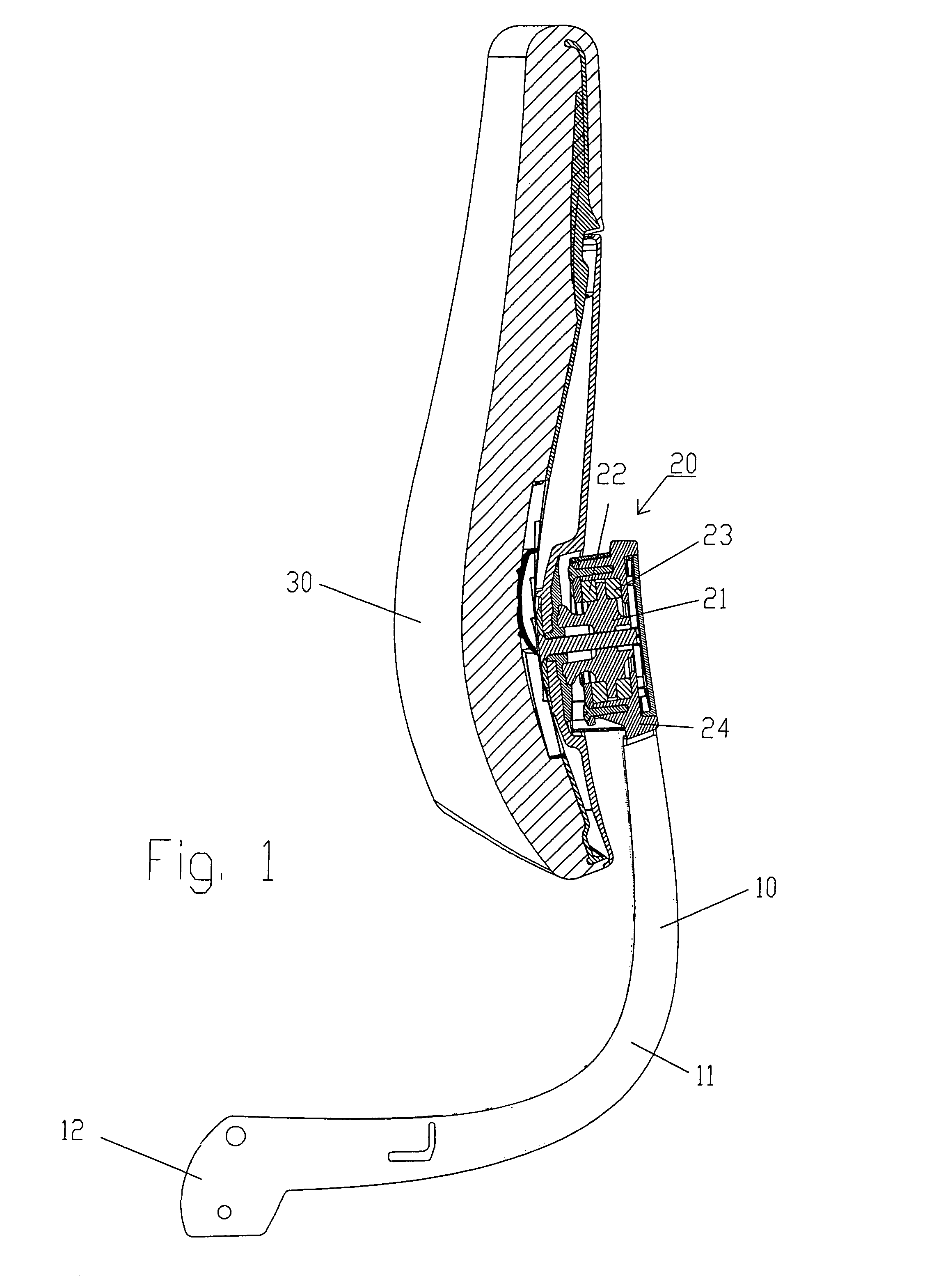
[0018]The back rest shown in the drawings is intended in particular for mounting on the lower frame (not shown) of an office chair. It comprises a back support 10, on which a back surface 30 is fastened and can swivel via a joint 20.

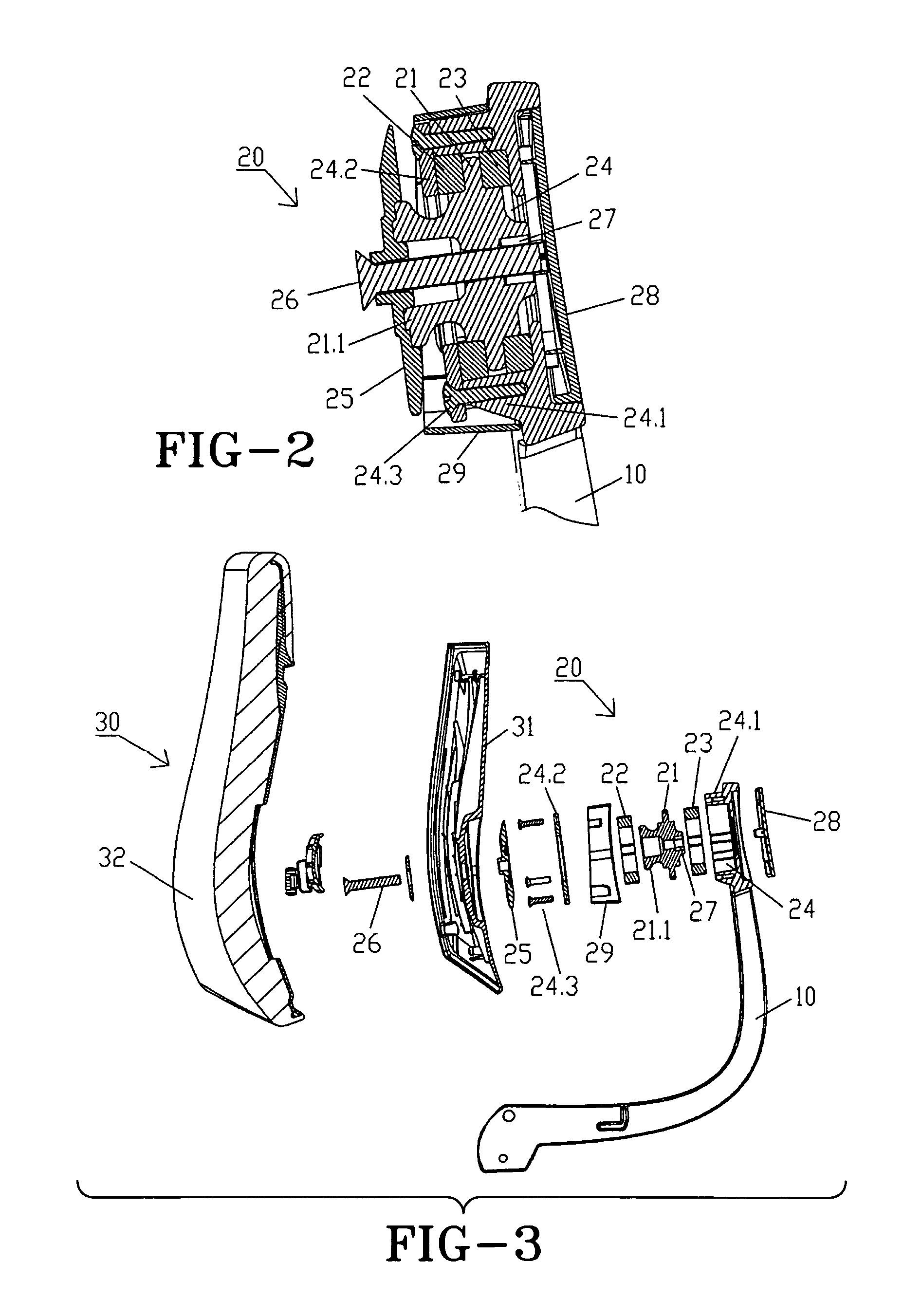
[0019]The back support 10 is formed by two support rods 11, roughly parallel to each other, of which the rear rod 11 can be seen in FIGS. 1 and 3. The support rods 11 are joined by their lower free ends 12 to the aforesaid lower frame. In the area of their upper end, the two support rods 11 are joined to each other and also to a pot-shaped part 24.1 of a receiving chamber 24 of the joint 20, enclosing the pot-shaped part 24.1 of the receiving chamber 24 in U-shaped manner.

[0020]The joint 20 moreover includes a joint plate 21, which is embedded in the receiving chamber 24 between two ring-shaped elements 22 and 23 and is itself ring-shaped, due to a central continuous hole. The ring-shaped elements 22, 23 are made of an elastic as well as compressible mat...


PUM


Abstract

A back rest for a chair with a back support and a back surface secured to the back support and able to swivel about a two-axis joint. The joint has a joint plate connected to the back surface, an element made of an elastic material that supports the joint in a ground position, and a chamber to accommodate the elastic element, connected to the back support. The joint plate is arranged in the receiving chamber between two elements made from an elastic material, holding the joint in a ground position and each being supported against the receiving chamber, and it can swivel about the two swivel axes. When the joint is placed under load, the two elastic elements are only subjected to compression. There are no tension-loaded connections which break under loading and can result in the joint falling apart.

Description

CROSS-REFERENCE TO RELATED APPLICATIONS[0001]This application claims foreign priority based on German Patent Application No. 10 2006 049 677.9, filed on Oct. 18, 2006, the content of which is incorporated herein by reference in its entirety.BACKGROUND OF THE INVENTION[0002]1. Field of the Invention[0003]The present invention relates to a back rest for a chair with a back support and a back surface secured thereto and which is able to swivel about a two-axis joint, wherein the joint has a joint plate connected to the back surface, an element made of an elastic material that supports the joint in a ground position, and a chamber to accommodate the elastic element, connected to the back support.[0004]2. Description of the Prior Art[0005]A back rest of this kind is known from EP 0 935 934 A2, where the joint comprises two joint plates, also referred to as end plates. One of these end plates is connected by a screw to the back surface. The second end plate is connected by a screw to the ...

Claims


Application Information

Patent Timeline
Patent Type & Authority Patents(United States)
IPC IPC(8): A47C3/00
CPCA47C7/448Y10T403/32131
Inventor MAIER, PETERFISCHER, HARRY
Owner SEDUS STOLL
Why Eureka
Try Eureka