Winding structure of transformer

a transformer and winding technology, applied in the direction of transformer/react mounting/support/suspension, basic electric elements, electrical apparatus, etc., can solve the problems of occupying a large space and crowded inner space of the power supplier, and achieves improved connectivity, improved space arrangement, and improved service life.

Active Publication Date: 2009-02-17
ZIPPY TECH
View PDF6 Cites 25 Cited by
  • Summary
  • Abstract
  • Description
  • Claims
  • Application Information

AI Technical Summary

Benefits of technology

[0003]Therefore, since the conventional transformer structure might meet the problem of insufficient space as mounting in the power supplier, the object of the present invention is to provide an improved transformer structure for achieving a better space arrangement.
[0004]The present invention is related to a winding structure of a transformer, which is constructed by at least a core, at least a primary winding coil and a secondary winding coil, wherein the primary winding coil and the secondary winding coil are respectively wound around the core and are separated by an insulating layer; and the secondary winding coil has a winding portion wound around the core through at least a circle, so as to define two winding terminals, wherein each winding terminal of the winding portion is connected with an extending section, which is extended to the outside of the transformer and is connected with an electricity connecting section at the rear end thereof, and the electricity connecting section has plural pins electrically welded on a circuit board, thereby the extending section and the electricity connecting section are crossing connected between the secondary winding coil and the circuit board so as to save the space on the circuit board for arranging the secondary winding coil. Here, the extending section also can be connected with at least a rectification switch. Besides, the extending section can further increase the connect area with the air for achieving a heat-dispersing effect.

Problems solved by technology

However, all the elements have to be welded on a circuit board, which has a universal standard in general power supplier, so that the increased power causes the inner space of the power supplier more and more crowded.
Since the conventional transformer 1 needs to arrange several strips of copper foils 2 for outputting, a lot of space will be occupied so as to narrow the available space and complicate the element arrangement.
Another problem is heat-dispersing.

Method used


Image

  • Winding structure of transformer
  • Winding structure of transformer
  • Winding structure of transformer

Examples


Embodiment Construction

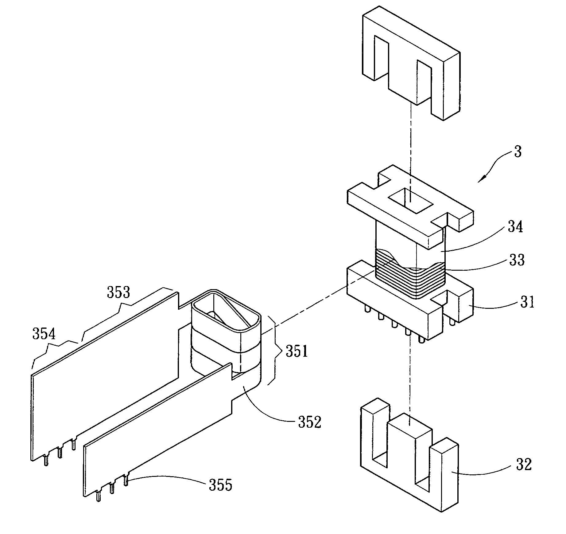
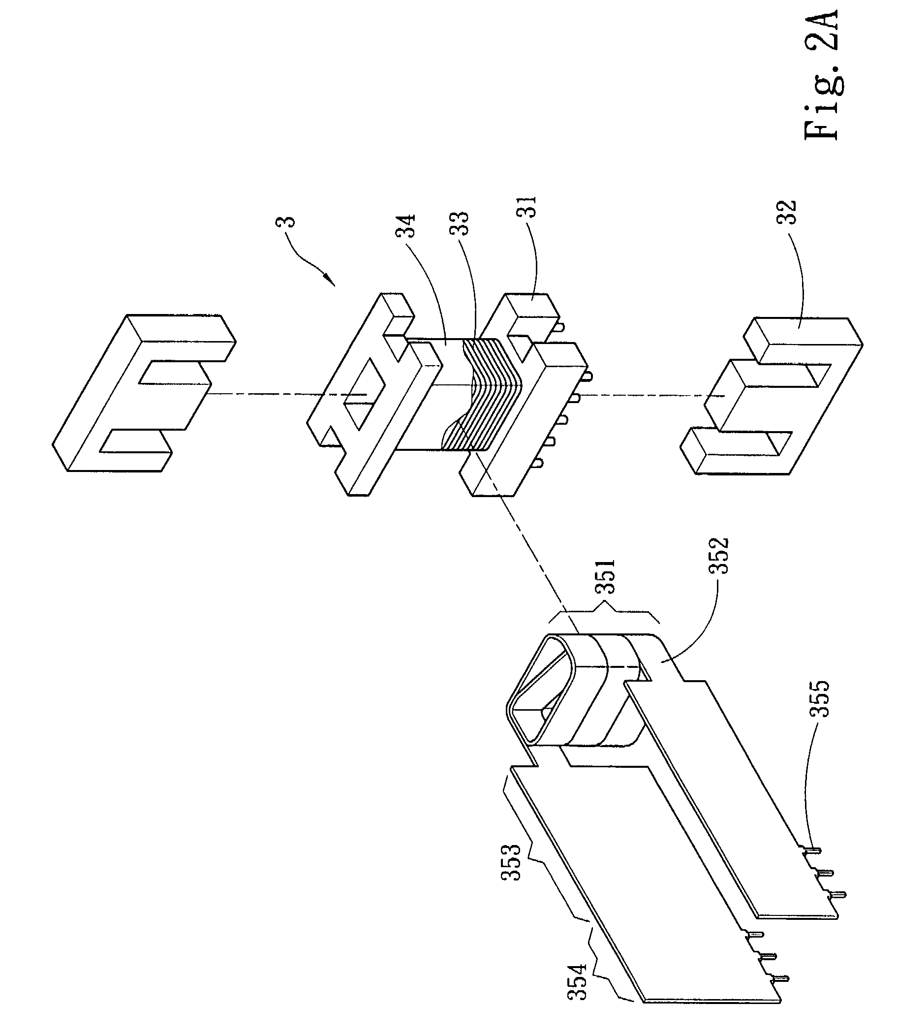
[0012]Please refer to FIG. 2A and FIG. 2B, which are respectively a decomposition drawing and a three-dimensional drawing showing a preferred embodiment according to the present invention. The present invention is related to a winding structure used for a transformer which includes at least a core 32, a primary winding coil and a secondary winding coil, wherein the winding coils are magnetically coupled through the core 32 to form a transformer 3. Moreover, a frame 31 is further included between the core 32 and the primary and the secondary winding coils. In this embodiment, a coil 33 is used as the primary winding coil, and the coil 33 is coated by an insulating layer 34. Then, the secondary winding coil is defined to have a winding portion 351 wound around the core 32, and the two ends of the winding portion 351 respectively are defined to be a winding terminal 352. Here, the winding terminals 352 are respectively connected with an extending section 353, which is extended from the...


PUM

PropertyMeasurementUnit
poweraaaaaaaaaa
winding structureaaaaaaaaaa
sizeaaaaaaaaaa

Abstract

The present invention discloses that a primary and a secondary winding coil are respectively wound around the core and are separated by an insulating layer; and the secondary winding coil has a winding portion wound around the core through at least a circle to define two winding terminals, wherein each winding terminal of the winding portion is connected with an extending section extended to the outside of the transformer and is connected with an electricity connecting section at the rear end thereof. The electricity connecting section has plural pins electrically welded on a circuit board, thereby the extending section that is connected with a rectification switch and increases the contact areas with the air for achieving a heat-dispersing effect and the electricity connecting section are crossing connected between the secondary winding coil and the circuit board to save the space on the circuit board for arranging the secondary winding coil.

Description

FIELD OF THE INVENTION[0001]The present invention is related to a winding structure of a transformer, wherein the secondary winding coil of the transformer is connected with an extending section and an electricity connecting section extended toward an opposite direction to the transformer for achieving a crossing conduction.BACKGROUND OF THE INVENTION[0002]Generally, a transformer includes a frame, a pair of assembled cores, and a primary and a secondary winding coils wound on the frame, wherein the frame has a longitudinal through hole for passing through the cores, the frame also has a winding area outside the through hole for winding leading wires so as to form the primary winding coil and the second winding coil which are separated by an insulating layer and whose winding terminals are respectively wound on the frame. As shown in R. O. C. Patent No. M242839, entitled “Improved Transformer Structure”, it includes a main body, several insulating pieces, a housing and primary and s...

Claims


Application Information

Patent Timeline
Patent Type & Authority Patents(United States)
IPC IPC(8): H01F27/29
CPCH01F27/29H01F27/06H01F27/08
Inventor CHANG, YU-YUAN
Owner ZIPPY TECH
Why Eureka
Try Eureka