
Dual mode personal locator beacon

a personal locator and beacon technology, applied in direction finders using radio waves, instruments, electric signalling details, etc., can solve the problems of less efficient sar systems for individuals, limited survival time in water, and thousands of people lost at sea every year, so as to reduce the transmission repetition rate of successive signals, save effort, cost and danger, and prolong the effect of plb

Active Publication Date: 2009-02-17
MOBIT TELECOM
View PDF20 Cites 61 Cited by
  • Summary
  • Abstract
  • Description
  • Claims
  • Application Information

AI Technical Summary

Benefits of technology

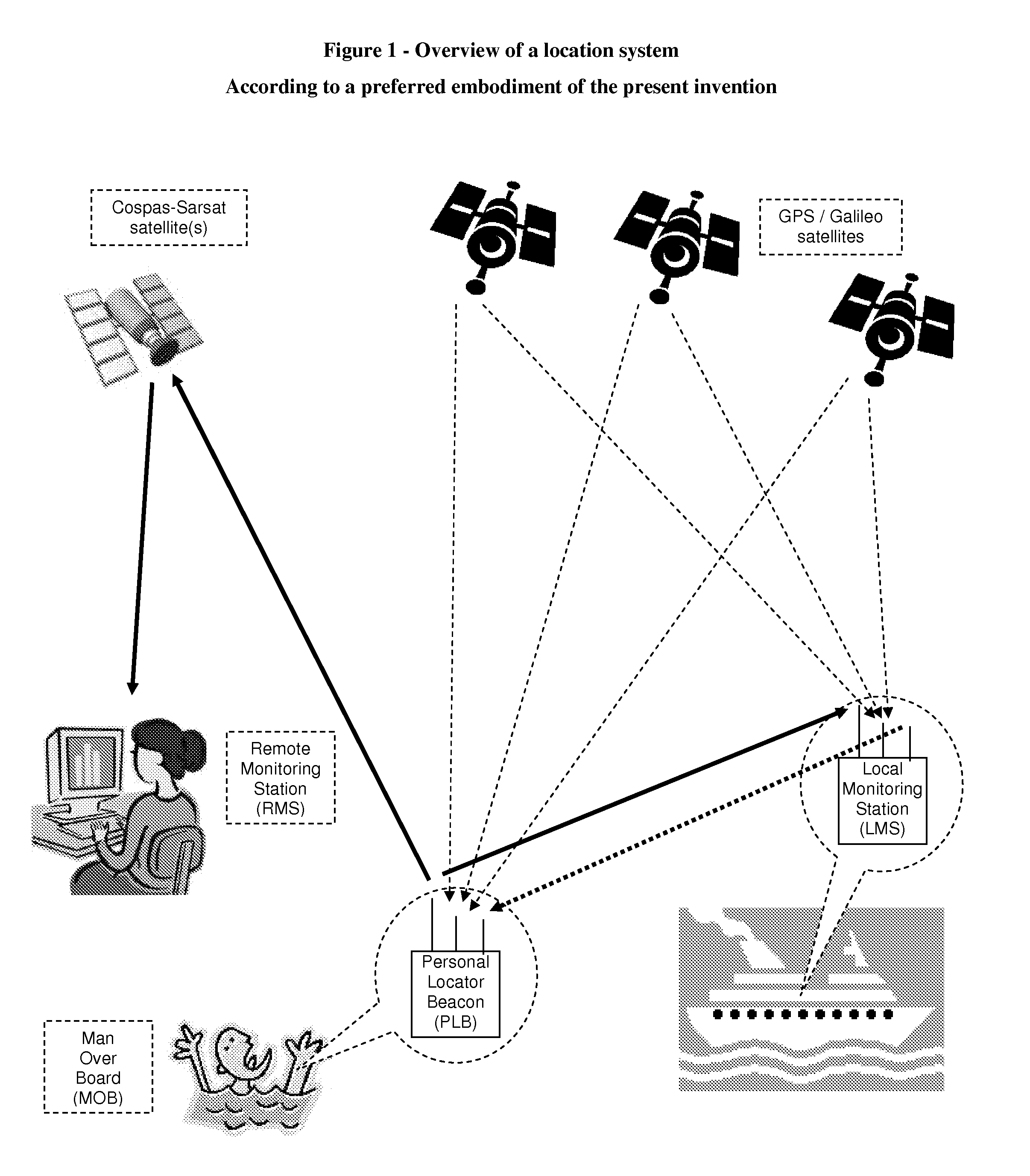
[0052]Possibly, among this first group of successive signals, at least one signal is configured to be transmitted at a higher transmission power compared to a previously transmitted signal. This way, there is a fair chance that the LMS will still detect the PLB signals, even if the distance between the PLB and LMS increases in time. On the other hand, the signal transmission power is not increased too early, in order to save battery power at the PLB.
[0054]Having a GNSS decoder coupled to the PLB enables to acquire the PLB speed, in addition to its current position. Then, it is possible to refine the PLB transmission power strategy, particularly among the first group of successive signals. Preferably, among the first group of successive signals, at least one signal is configured for a higher transmission power compared to a previously transmitted signal, and the difference between the transmission power of these couple of signals is larger as the PLB speed is higher.
[0056]Upon receiving an acknowledgement from the RMS, the PLB may further be configured to decrease the transmission repetition rate of successive signals, even bellow the currently set low repetition rate. This still enables updating the PLB position at the RMS, yet since the PLB was already detected, it could be desirable to trade off the position update rate with longer PLB battery life, utilizing the residual battery energy to transmit the same number of signals but spread over a longer time.
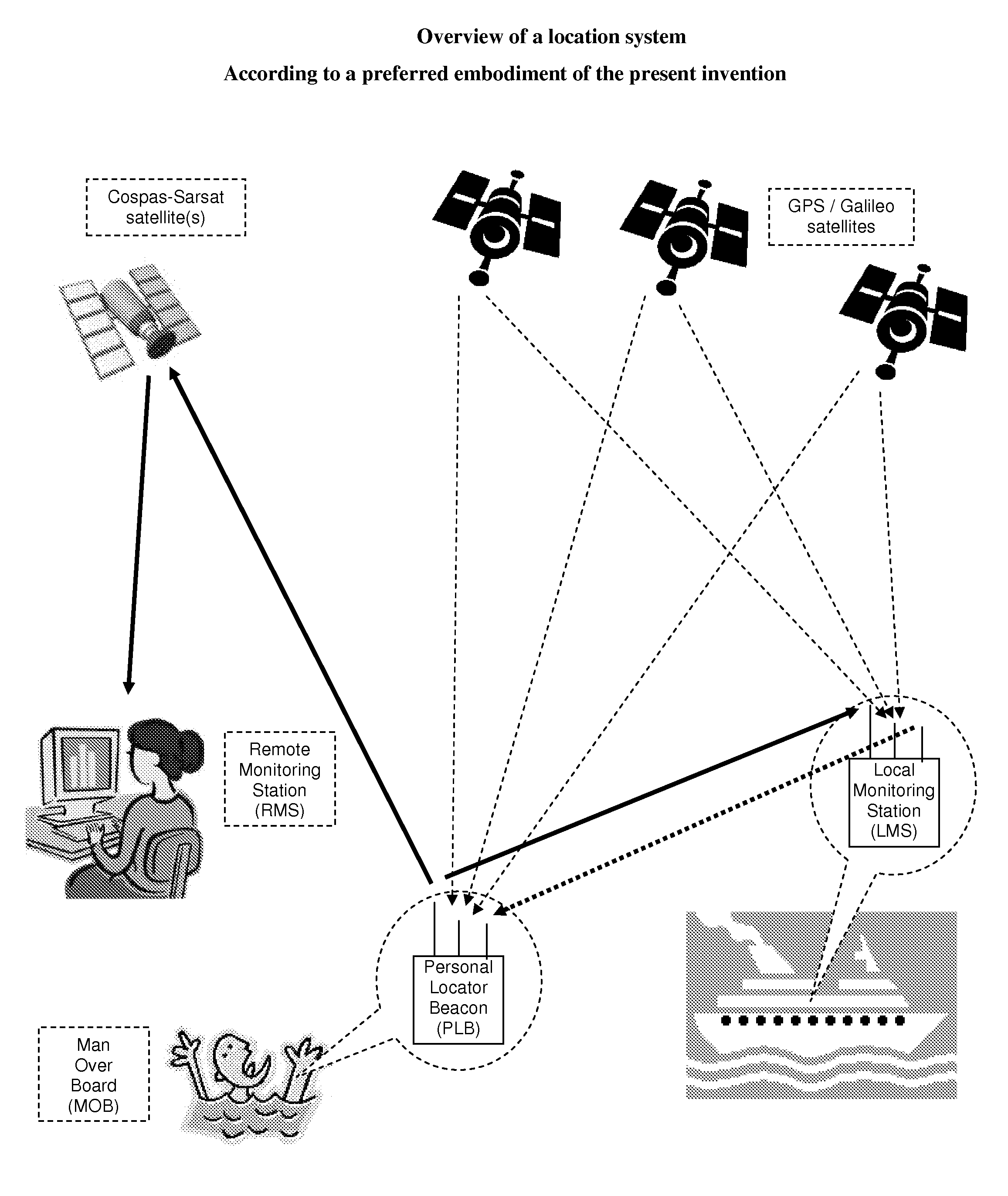
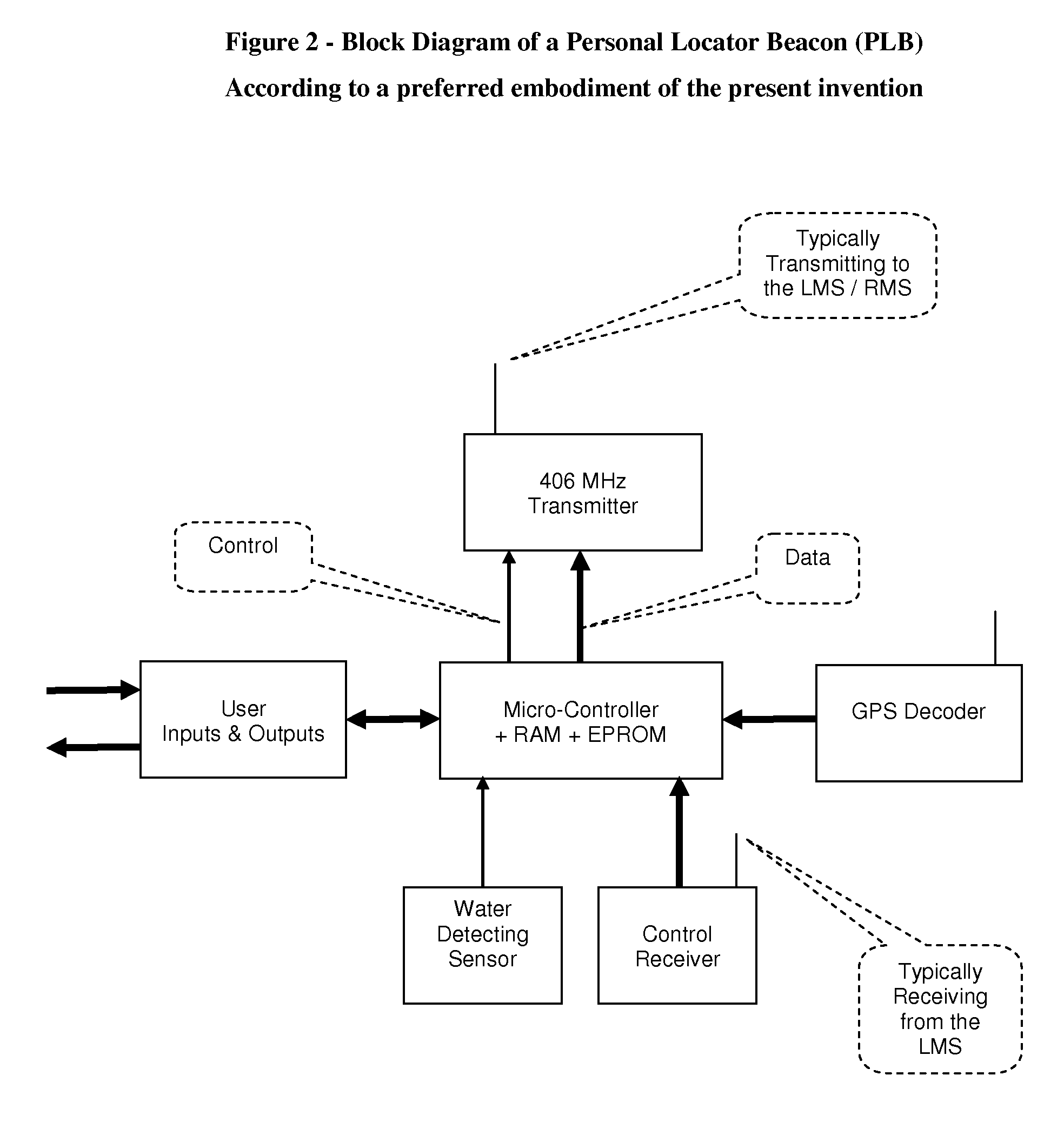
[0057]As a skilled person may appreciate, it would be desirable to be able to deactivate the PLB, i.e. cause it to cease transmitting, upon been detected and located by the LMS and after concluding the operation related with this location, e.g. rescue a lost person (or upon a false alarm). If this deactivation is conducted early enough, then the RMS would not be alerted, saving much efforts, cost and danger associated with a SAR operation directed by the RMS. It is possible to provide the PLB with an input enabling the user with a momentarily deactivation, preventing a permanent deactivation to be unintentionally invoked. Yet preferably, the present invention proposes a wireless remote control deactivation, directed from the LMS. It is assumed that an LMS operator is usually in a better condition to wisely operate the system, than a person bearing the PLB, often in distress. Therefore, the PLB preferably comprises a control receiver, and the LMS further comprises a compatible control transmitter, to control the PLB. These control signals may be employed for deactivating and / or activating the PLB, or for controlling PLB parameters such as the transmission power and repetition rate, or for acknowledging the PLB transmission (which can significantly encourage the PLB bearer). This wireless link between the LMS and the PLB may also be employed for providing the PLB with information about the LMS status, to enable activation of the PLB according to a differential reading of a parameter, e.g. the position of the LMS compared to the position of the PLB. It is also possible to configure the LMS to relay control signals from the RMS, to the PLB, via this control link.
[0060]Having a control receiver and a GNSS decoder at the PLB, and the LMS configured to transmit its position coordinates to the PLB, enables a further refinement of the PLB transmission power strategy, among the first group of successive signals. Then, it is possible that at least one signal be configured for a higher transmission power compared to a previously transmitted signal, and the difference between the transmission power of these couple of signals be larger as the speed of separation between the PLB and LMS is higher.

Problems solved by technology

Over a thousand people are lost at sea every year due to MOB accidents.
Fast detection and location of such accidents is crucial, since survival time in water is limited, typically less than two days at −20° C. and less than 6 hours at −10° C.
Still, present SAR systems are less efficient for individuals, specifically MOB.
Still, the problem of man overboard, which is very troublesome in the maritime arena, is not covered well enough by present art, including by present Cospas-Sarsat beacons.
Some of these MOB systems can accurately record the time and position of a MOB accident, however as the vessel sails away, and turns back to the recorded MOB position, or a SAR team is dispatched to this last reported location, the poor victim could have been drifted away, even by 100-200 meters, and without an accurate updated position report, it could be very difficult to locate and rescue this person in the water, particularly in poor visibility and high sea conditions.
This is a problem, since in case that a vessel is in the open sea, away from shore, the vessel from which a man fell overboard is the most relevant source for swift and effective rescue.
Apparently, incorporating present satellite beacons with present wearable MOB devices, could lead to the required solution, i.e. a wearable beacon detectable by both the satellites and the vessel.
But such an efficient dual mode MOB system is not straight forward, for several reasons.
One reason is that design considerations good for few satellite receivers (actually, satellites usually carry transponders, and much of the receiving process is done on earth) are not optimal for mass production receivers to be installed onboard ships, and unlike satellites, the vessel receiver may lack a line of site with an MOB transmitter.
Another reason for this non trivial incorporation is that current satellite PLB antennas are difficult to be conveniently worn by humans, while providing a good RF performance.
Obviously, a manual activation of an MOB PLB is not desirable, since the person overboard might be unable to activate the device, being unconscious, or almost frozen, or simply focused on keeping itself above the water level.
However, an automatic activation might cause many false alarms, e.g. when a person bearing the PLB innocently jumps to swim by the boat, or washes hands onboard.

Method used


Image

  • Dual mode personal locator beacon
  • Dual mode personal locator beacon
  • Dual mode personal locator beacon

Examples


second embodiment

Description of the Invention

General

[0134]According to a second embodiment of the present invention, the PLB is a location radio beacon, configured to be installed in 20 feet or 40 feet containers, carrying valuables on container ships or long haul tracks (semi-trailers or full trailers); the LMS is configured to be installed onboard a ship or track or in a port or hub or container depot; the RMS is at the headquarters of a shipping company, linked to a satellite communications system (“satcom”); the PLB is provided with a satcom transmitter, and the LMS is provided with a compatible receiver. Though the second embodiment PLB is not carried by a person, it is still named “Personal Location Beacon” (PLB), for consistency with the first embodiment terminology.

PLB Structure

[0135]FIG. 4 shows a Block Diagram of the second embodiment PLB. As a skilled person may observe, the blocks in FIG. 4 are a sub set of the blocks in FIG. 2 (first embodiment PLB). Differently than in the first embodi...


PUM


Abstract

A Personal Locator Beacon (PLB), supporting two operation modes local monitoring and remote monitoring. The apparatus includes a PLB that supports the present operation mode, as well as a local monitoring mode, employing the same transmitter, and automatically switching between modes. Upon activation, the PLB first tries to communicate with a local monitoring station, at a low transmission power, and at a high repetition rate, in purpose of dealing with the PLB call locally, without involving the remote monitoring station. Then, if not acknowledged by a local monitoring station, the PLB increases its transmission power, enabling access to a remote monitoring station. In a preferred embodiment, the PLB is carried by a person onboard a vessel, to alarm upon a Man Overboard (MOB) accident, the local monitoring station is installed onboard the same vessel, and the remote monitoring station is part of a satellite Search and Rescue (SAR) system, as Cospas-Sarsat.

Description

BACKGROUND OF THE INVENTION[0001]The present invention relates to wireless location systems, particularly for locating persons in distress or emergency situations.[0002]Though the scope of the present invention is far beyond a specific system or a specific application, it may be well understood by elaborating on the case of man overboard (MOB), i.e. a person that accidentally falls overboard a vessel to the sea (or ocean, or lake, or river, etc.).[0003]Over a thousand people are lost at sea every year due to MOB accidents. Fast detection and location of such accidents is crucial, since survival time in water is limited, typically less than two days at −20° C. and less than 6 hours at −10° C.[0004]A reliable device to detect and locate MOB is required to save lives, but also to provide the sailor with confidence and peace of mind, as well as reducing costs and risks of Search and Rescue (SAR) operations.[0005]The present art provides a reasonable solution for locating ships in danger...

Claims


Application Information

Patent Timeline
IPC IPC(8): G08B1/08G01S5/00H04B7/185B60Q1/00G01S19/17
CPCB63C9/0005G01S19/17G08B21/023G08B21/0269G08B21/028G08B21/088G01S5/0231
Inventor KATZ
Owner MOBIT TELECOM
Learn More