Cooling apparatus for flat display device

a technology for flat display devices and cooling apparatuses, which is applied in the direction of lighting and heating apparatus, electrical apparatus contruction details, electrical apparatus casings/cabinets/drawers, etc., can solve the problems of inability to stably operate flat display devices, ineffective heat dissipation to the external side, and malfunction of flat display devices, so as to effectively dissipate internal heat of flat display devices and reduce noise. , the effect of slimmer flat display devices

Active Publication Date: 2009-02-17
LG ELECTRONICS INC
View PDF19 Cites 20 Cited by
  • Summary
  • Abstract
  • Description
  • Claims
  • Application Information

AI Technical Summary

Benefits of technology

[0012]An object of the present invention is to provide a cooling apparatus for a flat display device, which is designed to make the flat display device slimmer and effectively dissipate internal heat of the flat display device.
[0013]Another object of the present invention is to provide a cooling apparatus for a flat display device, which can minimize noise and be manufactured with low costs.
[0014]Still another object of the present invention is to provide a cooling apparatus for a flat display device, which can minimize noise and improve heat dissipation efficiency by allowing internal air of the flat display device to be exhausted by natural convection.
[0015]Still yet another object of the present invention is to provide a cooling apparatus for a flat display device, which can improve a degree of installation free of the display device by improving an airflow direction in the flat display device.
[0016]Still yet another object of the present invention is to provide a cooling apparatus for a flat display device, which can enhance strength of a back cover by improving location and structure of holes formed on the back cover.

Problems solved by technology

Therefore, if the high temperature heat is not quickly dissipated, the display device may malfunction.
However, although the cooling effect for the specific component can be expected, the heat is not effectively dissipated to the external side.
Therefore, the flat display device cannot be stably operated.
That is, the internal temperature of the flat display device increases to deteriorate the performance of the flat display device.
In this case, although the heat collected in the display device can be effectively discharged to the external side, excessive noise is generated during the operation of the axial fan.
In addition, due to a gap between the axial fan and the flat display module and a thickness of the axial fan, an overall thickness of the flat display device increases.
The holes of the back cover deteriorate strength of the back cover.
In this case, the manufacturing cost increases.

Method used


Image

  • Cooling apparatus for flat display device
  • Cooling apparatus for flat display device
  • Cooling apparatus for flat display device

Examples


first embodiment

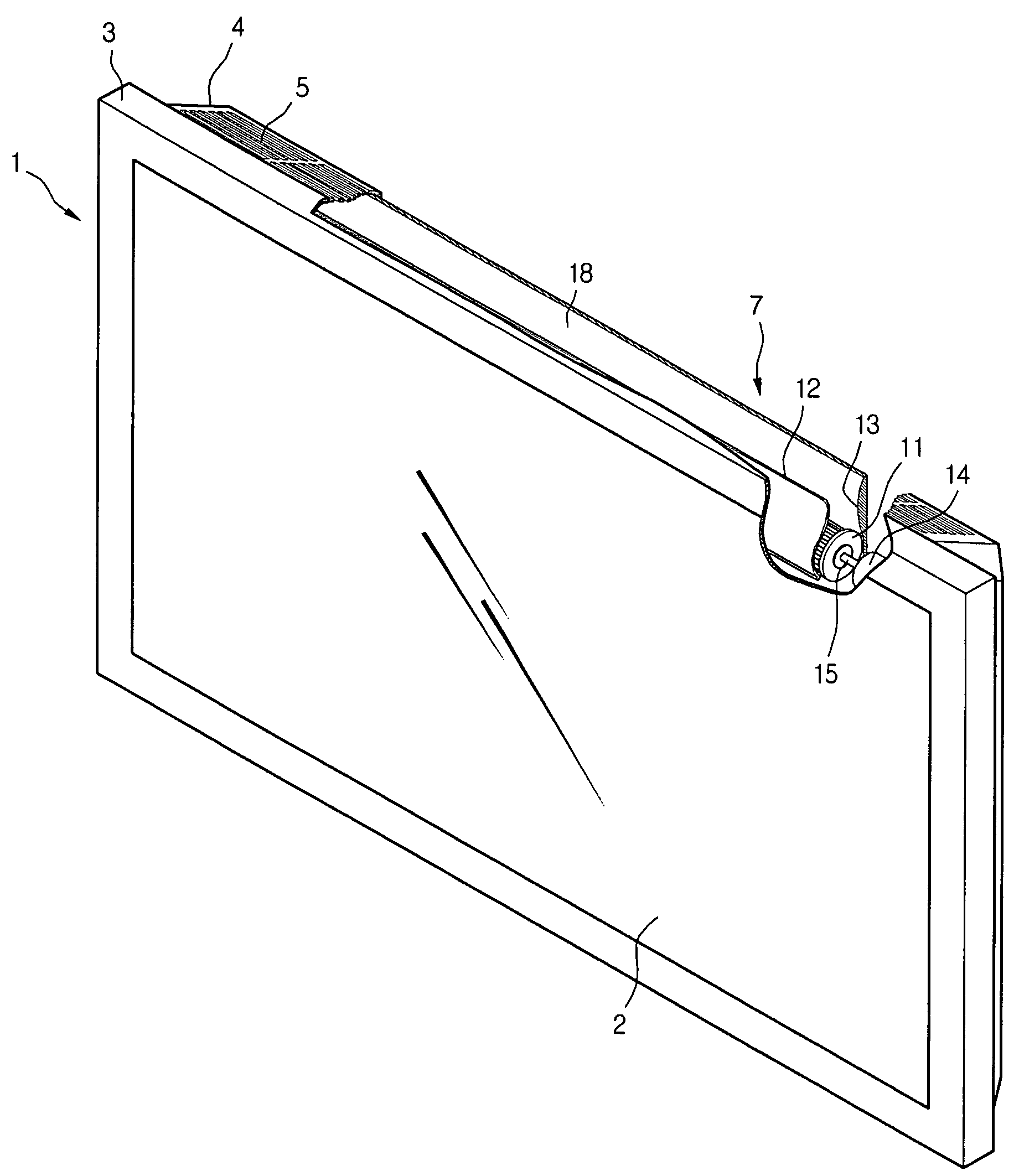
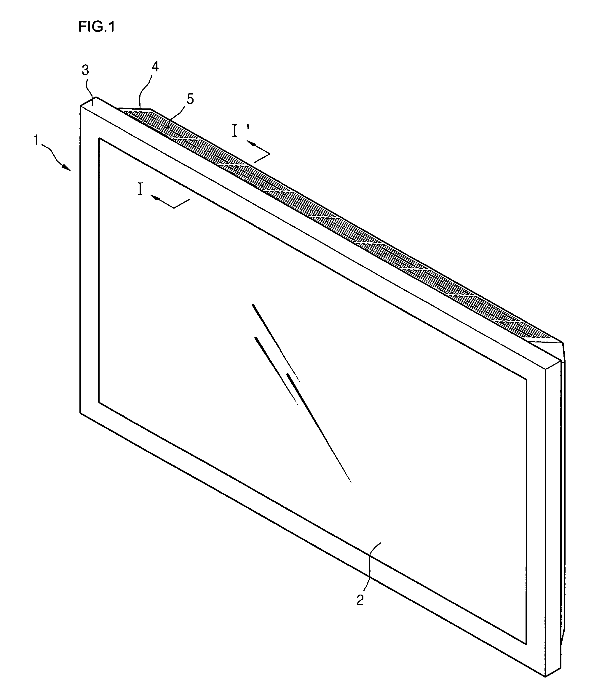
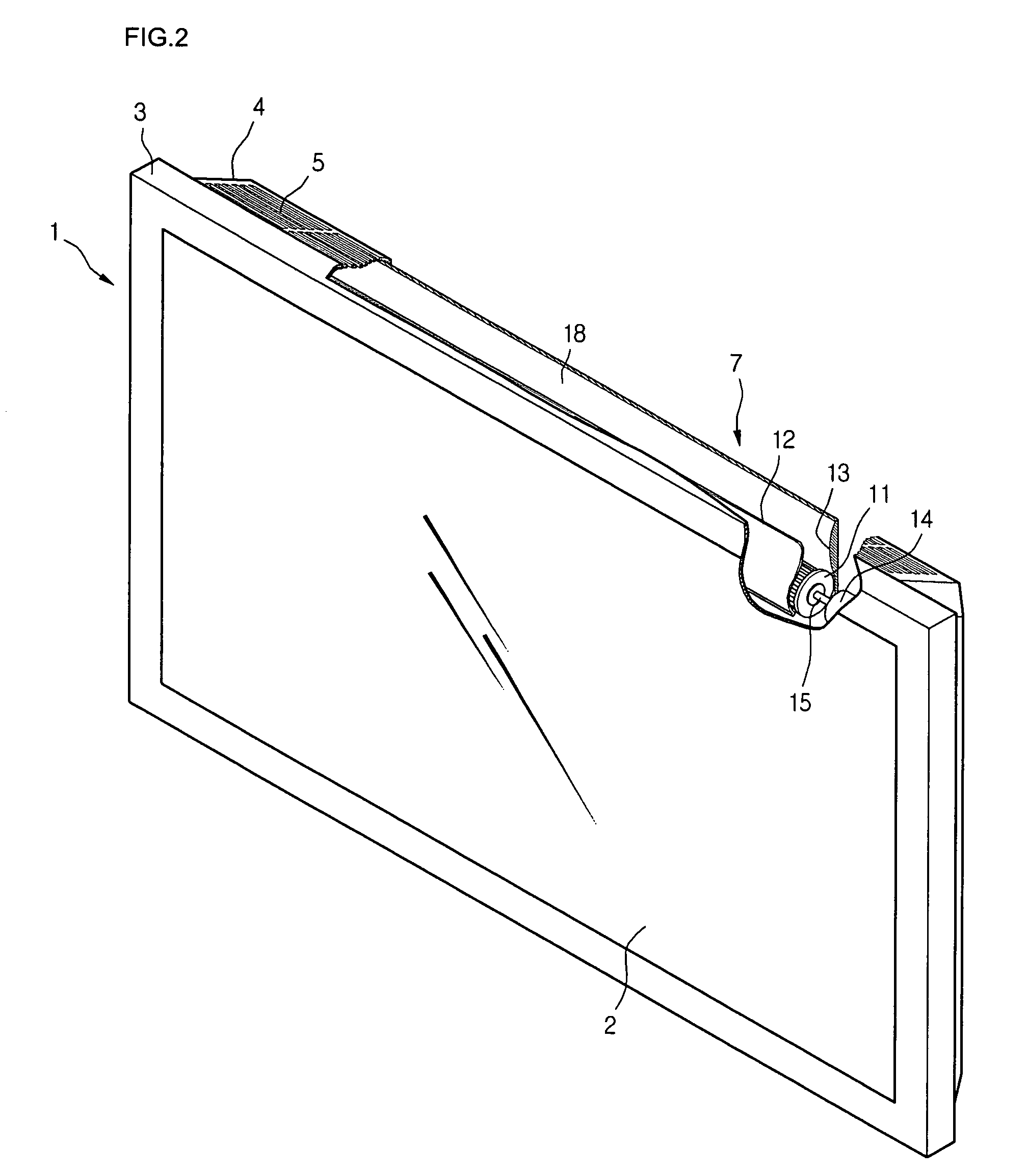
[0037]FIG. 1 is a perspective view of a flat display device according to an embodiment of the present invention.

[0038]Referring to FIG. 1, a flat display device 1 of this embodiment includes a flat display module 2, a front cover 3 for supporting and protecting a front portion of the flat display module 2, and a back cover 4 for supporting and protecting a rear portion of the flat display module 2. An air outlet 5 through which internal hot air of the flat display device 1 is exhausted is formed on an upper frame of the back cover 4. The air outlet 5 has a plurality of slits. The slits are arranged not to deteriorate strength of the back cover 4. That is, the slits are collected in an area of the air outlet 5.

[0039]The flat display module 2 may be selected from the group consisting of an LCD, an FED, a PDP, and an EL. Preferably, the flat display module 2 may be the PDP generating high temperature heat.

[0040]The front and back covers 3 and 4 define a space for receiving the flat dis...

second embodiment

[0068]FIG. 6 is a rear view of a flat display device according to another embodiment of the present invention. The flat display device of this embodiment is substantially identical to that of FIG. 1 except for the locations of the air inlet and outlet.

[0069]Referring to FIG. 6, an air inlet 21 is formed on an upper inclined portion of the back cover 4 while an air outlet 22 is formed on a lower inclined portion of the back cover 4. The cross-flow fan 7 is disposed right above the air outlet 22.

[0070]According to this embodiment, it cannot be expected to realize the airflow by the natural convection. However, since the hot air is exhausted downward, the possibility of directing the hot air to the user can be reduced. Furthermore, when the disposition of the components that require the thermal stability or generate high heat is limited due to a circuit arrangement of the flat display module 2, the locations of the air inlet and outlet can be properly adjusted.

[0071]Likewise the first ...

third embodiment

[0072]FIG. 7 is a rear view of a flat display device according to another embodiment of the present invention. The flat display device of this embodiment is substantially identical to that of FIG. 6 except for the locations of the air inlet and outlet.

[0073]Referring to FIG. 7, an air inlet includes first and second inlet portions 31 and 32 that are respectively formed on upper and lower inclined portions of the back cover 4. An air outlet33 is formed on a left portion (when viewed from a front portion of the display device).

[0074]Therefore, external air introduced through the upper and lower portions of the flat display device is exhausted through the air outlet 33 formed on the left frame portion.

[0075]According to this third embodiment, a degree of freedom in arranging the circuit of the flat display device can be improved. Likewise the foregoing embodiments, hot air is not directed toward the user. Furthermore, since the external cool air can be introduced through a relatively l...


PUM


Abstract

Provided is a cooling apparatus for a flat display device. The cooling apparatus includes a flat display module, a cover for protecting the flat display module, an air inlet formed on a portion of the cover to allow external air to be introduced into the cover, an air outlet formed on one of four frame portions of the cover to allow the air introduced through the air inlet to be exhausted out of the cover, and a fan for directing the air in a direction extending from a screen surface of the flat display device.

Description

BACKGROUND OF THE INVENTION[0001]1. Field of the Invention[0002]The present invention relates to a flat display device, and more particularly, a cooling apparatus for a flat display device, which can quickly dissipate internal heat to an external side.[0003]2. Description of the Related Art[0004]Unlike a cathode ray tube (CRT), a flat display uses a driving circuit arranged in a matrix pattern to differently excite pixels and thus realize an image. Recently, the flat display device has been widely used as it has advantageous in that it takes up a relatively small space. A variety of flat display modules such as a liquid crystal display (LCD), a field emission display (FED), a plasma display panel (PDP), and an electro-luminescence (EL) have been applied to the flat display device.[0005]The flat display device using the flat display module is reduced in a thickness as compared with the CRT. However, since a large number of heat-generating components must be incorporated in a narrow s...

Claims


Application Information

Patent Timeline
Patent Type & Authority Patents(United States)
IPC IPC(8): H05K7/20F28F7/00H05K5/00
CPCH05K7/20972H01J11/34H01J17/16H01J17/28
Inventor PARK, SANG DON
Owner LG ELECTRONICS INC
Why Eureka
Try Eureka