Non-invasive medical treatment installation

a non-invasive, medical treatment technology, applied in the field of non-invasive medical treatment, can solve the problem of significant limitation of the orbital movement capability of the x-ray c-arm

Inactive Publication Date: 2009-02-17
SIEMENS AG
View PDF9 Cites 5 Cited by
  • Summary
  • Abstract
  • Description
  • Claims
  • Application Information

AI Technical Summary

Benefits of technology

[0005]An object of the present invention is to provide a system for non-invasive medical treatment wherein the aforementioned disadvantage is avoided.
[0006]This object is achieved according to the invention by a therapy system having a carrier arm with a fixed end and a free end mounted on the therapy C-arm, the fixed end of the carrier arm being supported on the therapy C-arm between two end positions predetermined by the arc ends such that the carrier arm with its fixed end can move in an orbit. The carrier arm supports the therapy apparatus on its free end. The carrier arm is furthermore supported on the therapy C-arm such that it can rotate around a rotation axis, so it can be aligned at both end positions such that it extends beyond the respective arc end. The rotatable support of the carrier arm on the therapy C-arm ensures that such a projection beyond the arc end can also be produced in a simple manner at the other end position.
[0008]In a further preferred embodiment, the therapy apparatus is arranged such that its focus is located in a plane that runs parallel to and removed from the orbital plane of the therapy C-arm. This makes it possible to remove the effective location of the therapy apparatus from the orbital plane of the therapy C-arm and thereby to achieve even more freedom of movement in the region of the therapy C-arm for a person attending the patient. This embodiment is particularly advantageous when, for imaging accompanying a treatment, an x-ray C-arm is arranged coaxial, coplanar and with axial offset relative to the therapy C-arm, the focus of the therapy apparatus coinciding with the isocenter of the x-ray C-arm. In addition to the increased freedom of movement (already mentioned) for medical personnel, this achieves the advantage that the x-ray C-arm can in practice be moved orbitally without hindrance. In an arrangement of x-ray and therapy C-arms in which the orbital planes of both arcs coincide, the orbital movement capability of the x-ray C-arm is significantly limited, for example because x-ray source or x-ray receiver protrude into the movement path of the therapy C-arm.

Problems solved by technology

In an arrangement of x-ray and therapy C-arms in which the orbital planes of both arcs coincide, the orbital movement capability of the x-ray C-arm is significantly limited, for example because x-ray source or x-ray receiver protrude into the movement path of the therapy C-arm.

Method used


Image

  • Non-invasive medical treatment installation
  • Non-invasive medical treatment installation
  • Non-invasive medical treatment installation

Examples


Embodiment Construction

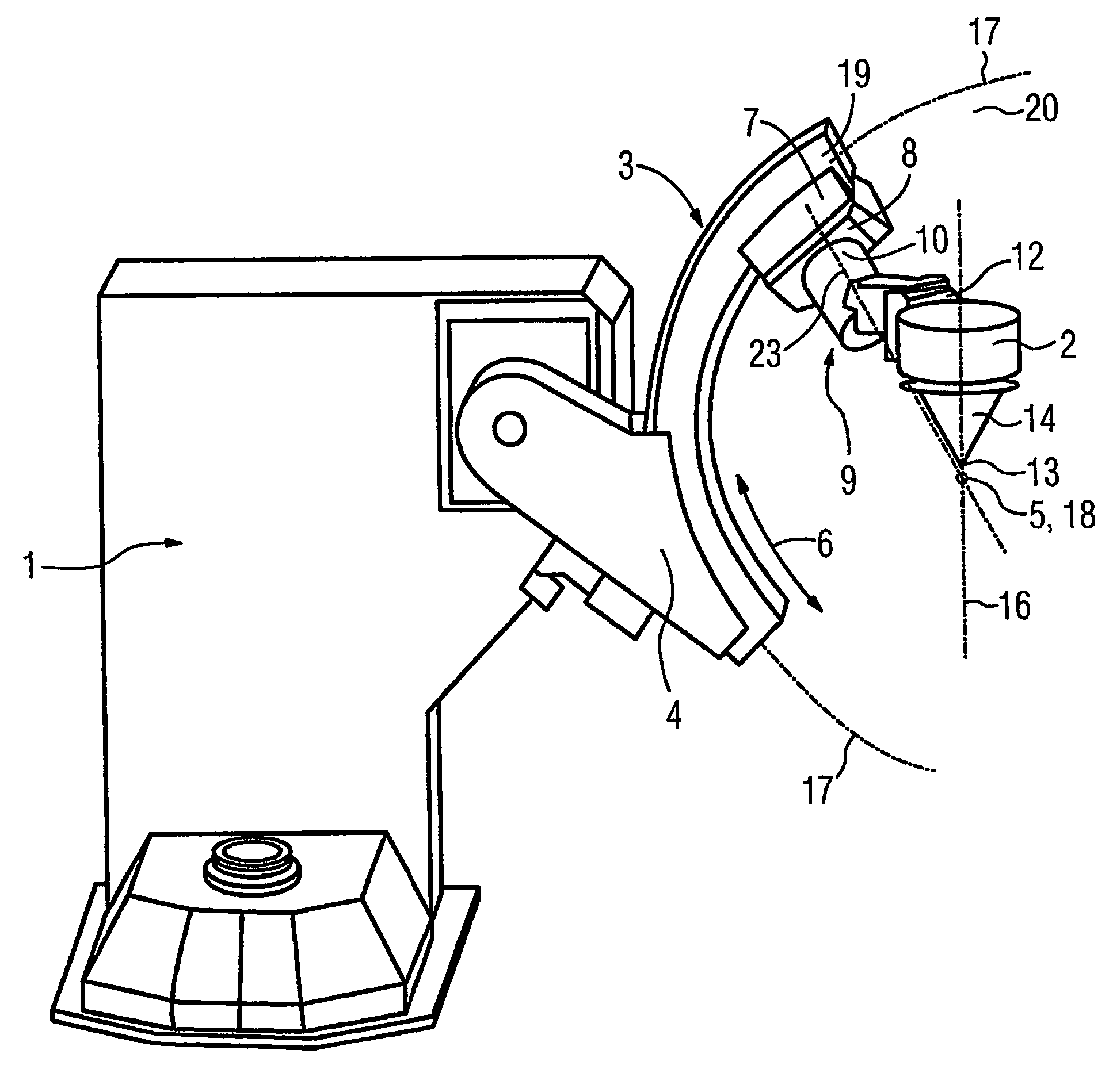
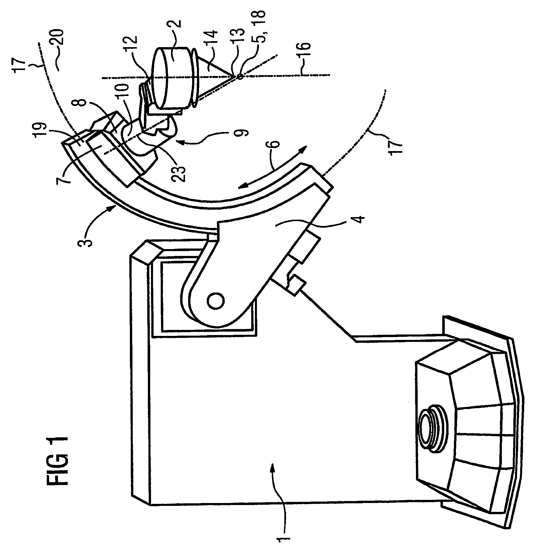
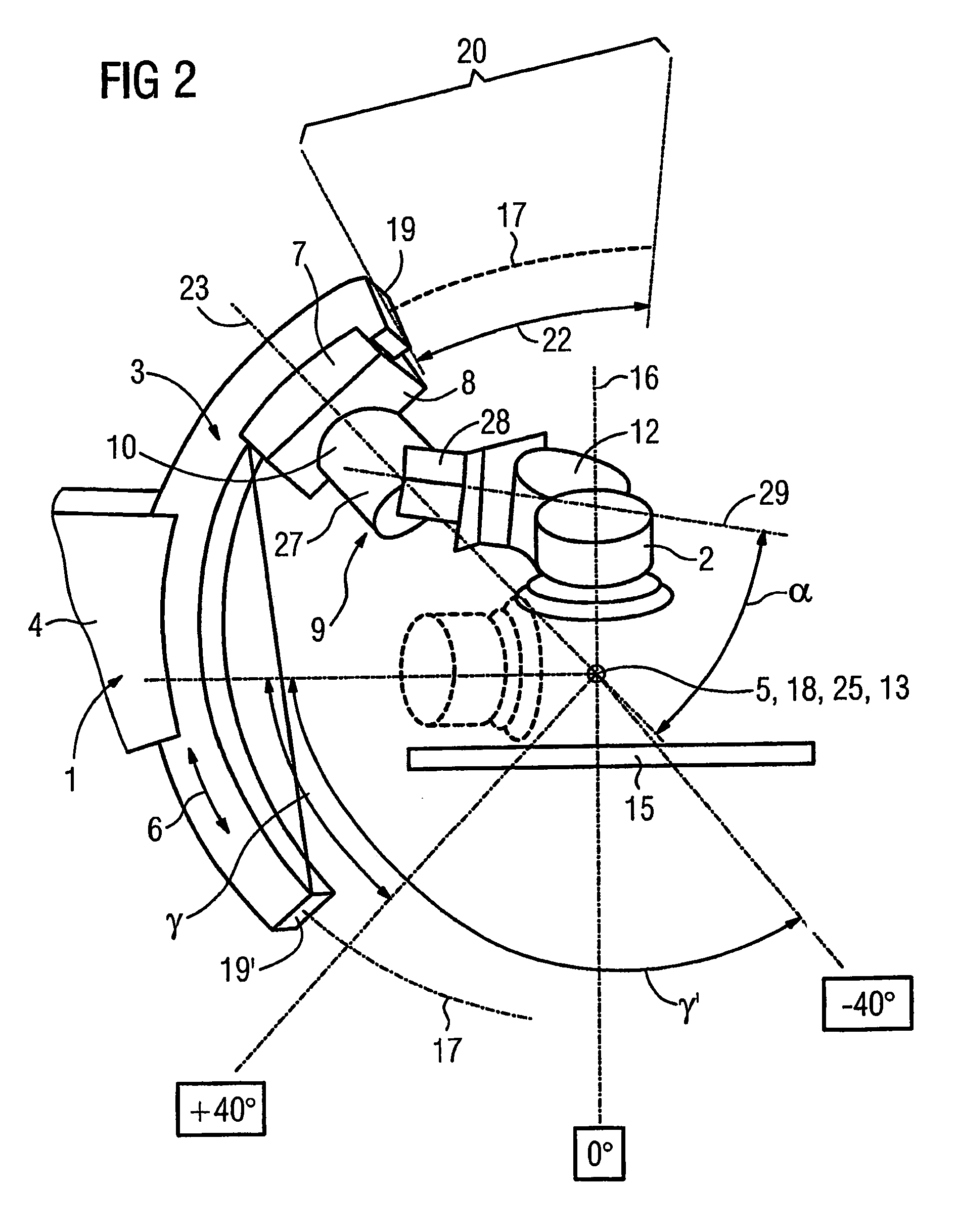
[0015]The system shown in the Figures has a base 1 on which is fixed a first C-arm that supports a therapy apparatus (for example the shockwave head 2 of a lithotripsy system). The first C-arm (designated in the following as therapy C-arm 3) is an annulus segment that can be orbitally moved on an extension arm 4 of the base frame 1 around its middle point or around its isocenter 5, which is indicated in FIG. 1 by the double arrow 6. A sled 7 is supported on the therapy C-arm 3 such that it can move orbitally (thus corresponding to double arrow 6). A carrier arm 9 is attached with its fixed end 10 on a side 8 of the sled 7 facing the isocenter 5. The free end 12 of the carrier arm 9 carries the shockwave head 2. Due to the orbital movement capability of the therapy C-arm 3 and the sled 7, the shockwave head 2 can be positioned in various angle positions relative to the isocenter 5 or to a patient table 15. The radial separation of the shockwave head 2 from the isocenter 5 is selected...


PUM


Abstract

A non-invasive medical treatment installation has a therapy C-arm mounted on a base, and defining an isocenter. A therapy apparatus having a focus is mounted at the free end of a carrier arm, that has a fixed end attached to the therapy C-arm. The mounting of the fixed end of the carrier arm to the therapy C-arm allows orbital movement of the carrier arm along the therapy C-arm between two final positions respectively delimited by the opposite ends of the C-arm. The carrier arm is mounted to the therapy C-arm to allow rotation of the carrier arm around a rotational axis, so that when the carrier arm is at either of said final positions, it extends beyond the respective end of the C-arm.

Description

BACKGROUND OF THE INVENTION[0001]1. Field of the Invention[0002]The present invention concerns a system for non-invasive medical treatment of the type wherein a therapy apparatus (such as a shockwave head in the case of a lithotripsy treatment) is moved on an orbit around a patient table or around a patient on this patient table.[0003]2. Description of the Prior Art[0004]A body region of the patient to be treated in a system of the above type is arranged in the isocenter of the orbit. The focus of the therapy apparatus (in the case of a shockwave head thus the focus of the ultrasonic waves emanating therefrom) is located in the isocenter or in the body region to be treated. A circular arc, known as a C-arm, is generally used for guidance of the therapy apparatus. In the case of a C-arm that is permanently fixed at a base, this C-arm must exhibit an arc length that is at least as large as the desired movement path of the therapy apparatus. The arc length of the C-arm can be shortened...

Claims


Application Information

Patent Timeline
Patent Type & Authority Patents(United States)
IPC IPC(8): A61B5/05A61B17/22
CPCA61B17/2255
Inventor KALTSCHMIDT, RAINERWILL, ULRICH
Owner SIEMENS AG
Why Eureka
Try Eureka