
Method and system for vibration signal processing

a signal processing and vibration technology, applied in the direction of fluid pressure measurement by mechanical elements, vibration measurement in solids, amplifier modification to reduce noise influence, etc., can solve the problems of high cost, high cost, and long duration of low-frequency vibrations, and achieve the effect of intensive signal processing and digital implementation

Inactive Publication Date: 2009-02-17
GENERAL ELECTRIC CO
View PDF2 Cites 16 Cited by
  • Summary
  • Abstract
  • Description
  • Claims
  • Application Information

AI Technical Summary

Benefits of technology

"The present invention relates to a method and system for processing vibration signals. The method involves obtaining electrical vibration signals, converting them into digital vibration samples, and dividing them into equal time intervals. The average absolute amplitude of the digital vibration samples is determined for each time interval and a time waveform is created by processing the samples as if they were independently-detected signals. The system includes a conditioning circuit, a high-pass filter, an analog-to-digital converter, an averaging circuit, and a buffer to receive and output the averaged digital vibration samples. The invention allows for accurate and efficient analysis of vibration signals for various applications such as machine condition monitoring and fault detection."

Problems solved by technology

Unfortunately, when taking vibration readings, these vibration events are overwhelmed by the prominent long duration of low-frequency vibrations.
One disadvantage in demodulation is that, due to the number of filter stages, its digital implementation requires intensive signal processing.

Method used


Image

  • Method and system for vibration signal processing
  • Method and system for vibration signal processing
  • Method and system for vibration signal processing

Examples


example

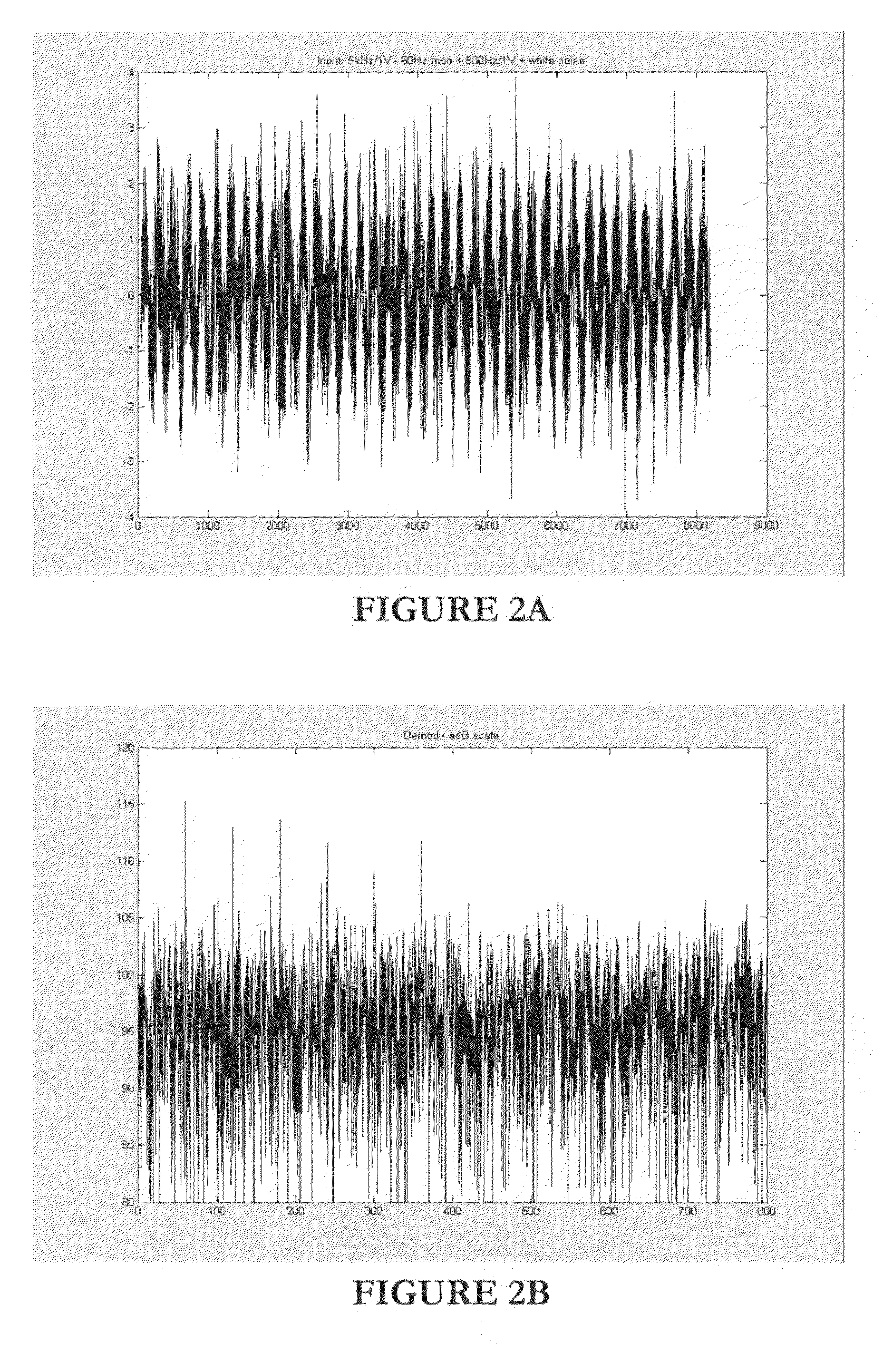
[0046]The above method of the present invention was simulated and compared against a classic demodulation process and the prior art PeakVue process. The simulation was based on a worst-case type of test signal, shown in FIG. 2A. Specifically, the signal included a 1V low-frequency noise at 500 Hz 1 dB white noise and a simulated 60 Hz impact signal. The simulated impact signal was a 1V, 5 kHz sinusoid passed through a Blackman-Harris window with a duration of 5 ms.

[0047]The result of classic demodulation is shown in FIG. 2B, the result of PeakVue processing is shown in FIG. 2C and the result of the method of the present invention is shown in FIG. 2D. Although all processes picked up the 60 Hz impacting signal, the method of the present invention provided the best SNR of ˜15 dB, compared to PeakVue's 12 dB and classic demodulation's 10dB SNR.


PUM

PropertyMeasurementUnit
frequencyaaaaaaaaaa
frequenciesaaaaaaaaaa
timeaaaaaaaaaa

Abstract

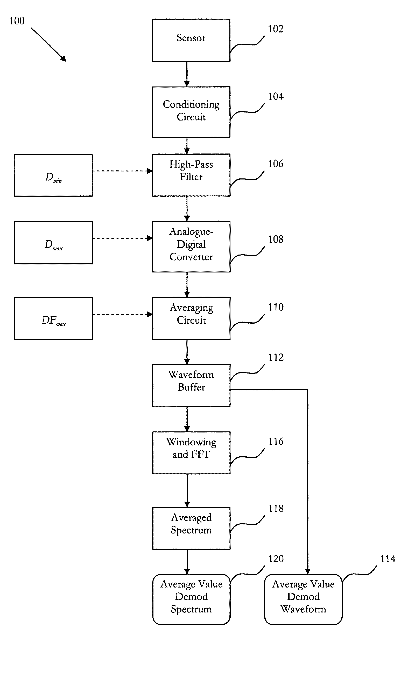
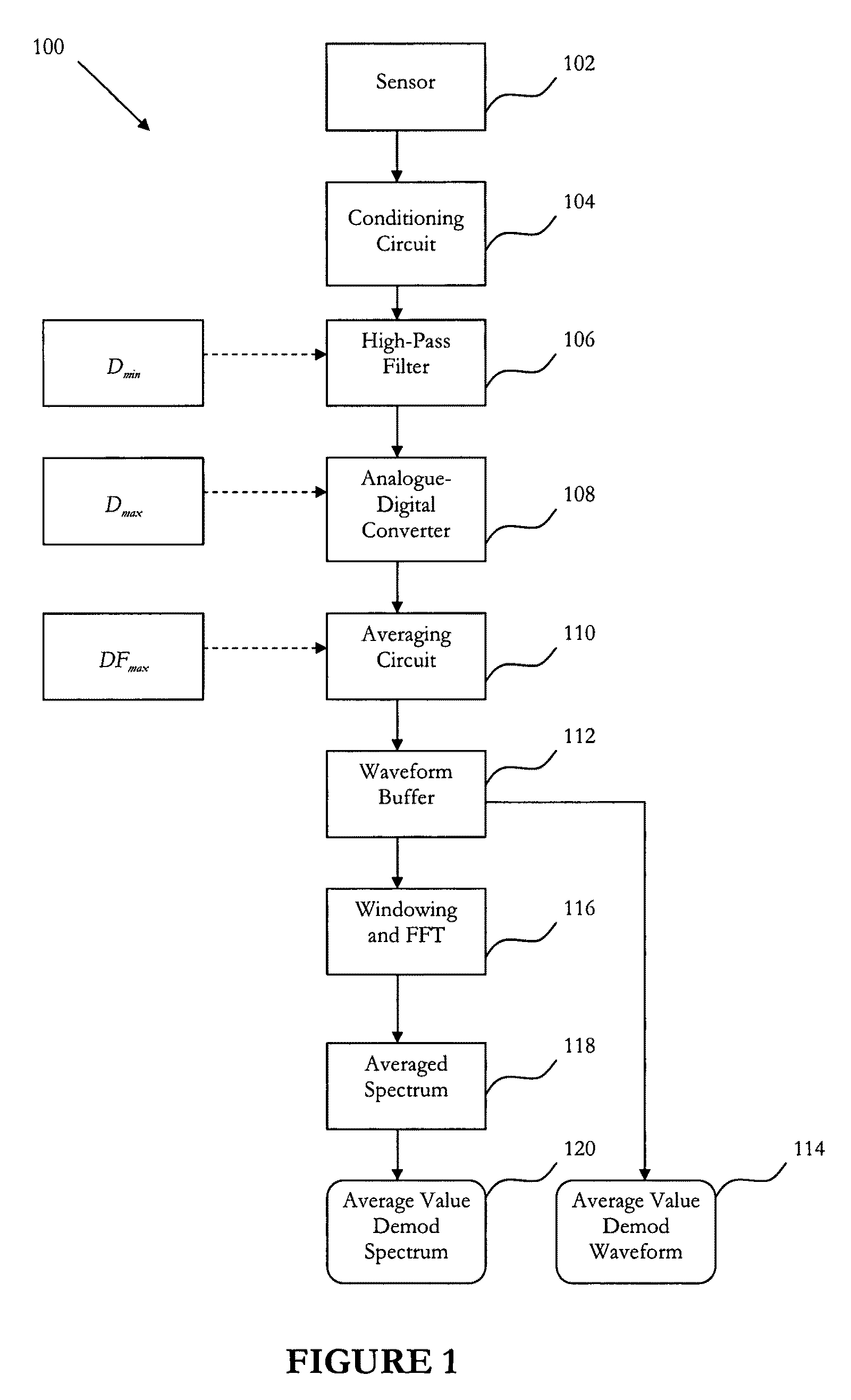
The present invention relates to a vibration signal processing method and system that can be used to account for situations where impact or impulse events are hidden in a normal vibration reading by low frequency vibrations and high frequency noise. In one preferred form, the method of the present invention comprises the steps of obtaining electrical vibration signals that represent mechanical vibrations of a machine (102-106), converting the electrical vibration signals into digital vibration samples (108), dividing the digital vibration samples into equal time intervals and determining the average absolute amplitude of the digital vibration samples for each time interval (110), generating a time waveform comprising the determined average amplitudes (112, 114), and processing the time waveform as if it were an independently-detected signal (116-120).

Description

FIELD OF THE INVENTION[0001]The present invention relates to a method and system for vibration signal processing. In particular, but not exclusively, the present invention relates to a method and system for machine fault detection using a demodulation process to account for situations where impact or impulse events are hidden in a normal vibration reading.BACKGROUND TO THE INVENTION[0002]Demodulation is a vibration analysis process used to account for situations where certain machine problems remain hidden in a normal vibration reading, preventing early corrective action. Usually, these situations arise when the vibration is associated with an impact or impulse event. These events have a high frequency but a short duration. Unfortunately, when taking vibration readings, these vibration events are overwhelmed by the prominent long duration of low-frequency vibrations.[0003]In use, demodulation first removes the low-frequency components of the vibration signals using a high-pass filte...

Claims


Application Information

Patent Timeline
Patent Type & Authority Patents(United States)
IPC IPC(8): G06F19/00G06F17/00G01F23/00G01L7/00G01N11/00
CPCG01H1/003G01M7/025
Inventor LEIGH, NIGELOMUNDSEN, CARL
Owner GENERAL ELECTRIC CO
Learn More