
Method of evaluating checks deposited into a cash dispensing automated banking machine

a cash dispensing machine and automatic technology, applied in automatic teller machines, atm details, instruments, etc., can solve the problems of user's frequent incurring a "bad check" fee, affecting the reliability of the system, and affecting the accuracy of the system

Inactive Publication Date: 2009-02-24
DIEBOLD SELF SERVICE SYST DIV OF DIEBOLD NIXDORF INC
View PDF7 Cites 127 Cited by
  • Summary
  • Abstract
  • Description
  • Claims
  • Application Information

AI Technical Summary

Benefits of technology

[0025]It is a further object of an example embodiment of the present invention to provide a deposit accepting apparatus that has greater reliability.
[0026]It is a further object of an example embodiment of the present invention to provide a deposit accepting apparatus that is more compact.
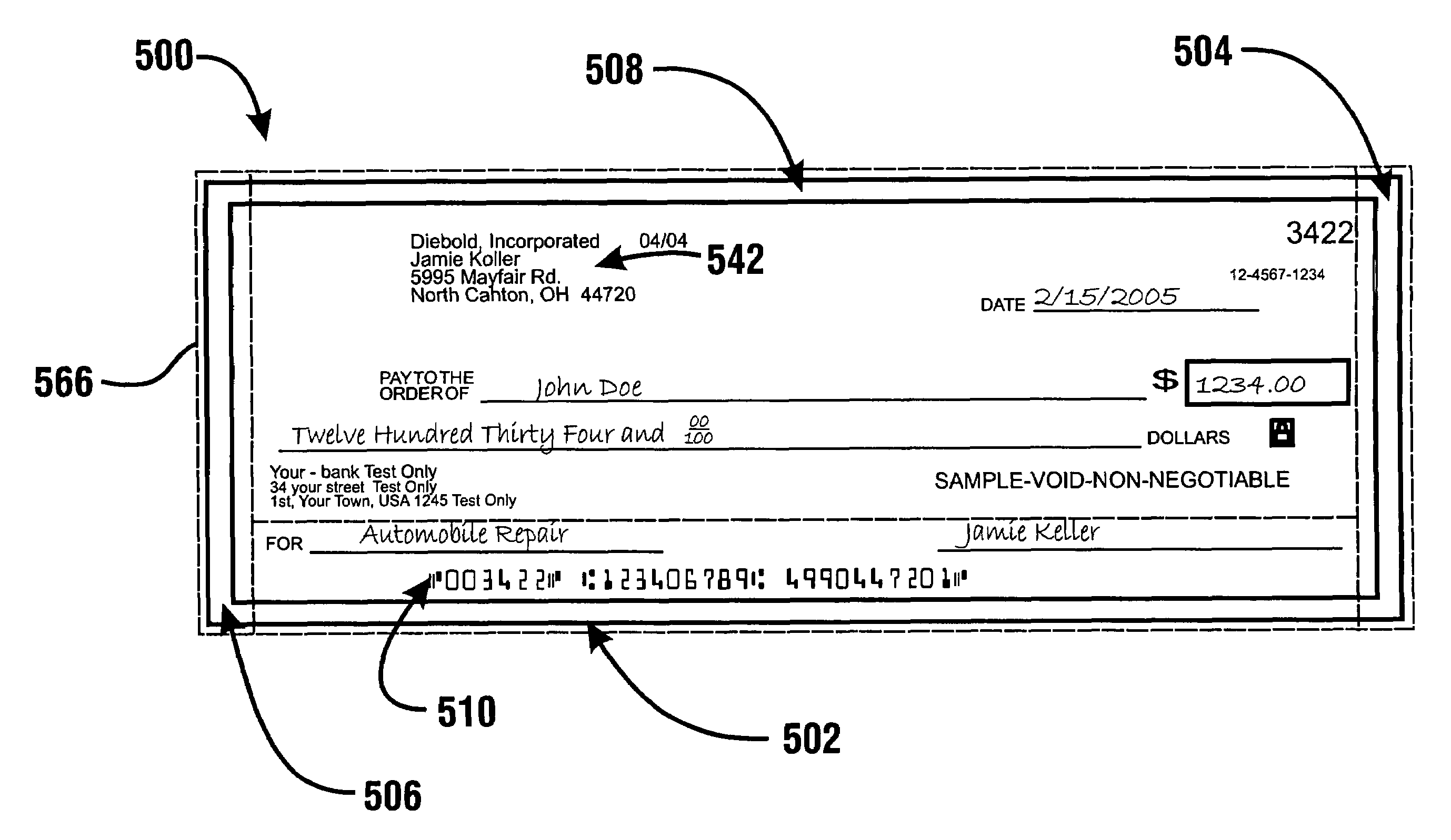
[0045]In the example embodiment the depository apparatus is also operative to sense for the presence of magnetic coding in appropriate locations on the check. For example the computer is operative to verify that the ink in the area which has been identified as including the MICR coding has magnetic properties. This may provide greater assurance that the document presented is in fact a genuine printed check and not a photocopy of a check. The computer may operate in addition to sense magnetic or other properties from various areas appropriate for the deposited document depending on data stored in memory. Further in some alternative embodiments the computer may operate to look for magnetic or other properties in areas of the check where such properties would not be appropriate. Such sensing may reduce the risk of the machine accepting fraudulent checks. Other embodiments may include read heads or other devices for reading features on a check corresponding to MICR line characters or other features magnetically.
[0048]In response to the host computer determining that the requested check cashing transaction is suitable to be carried forward, an authorization message is returned from the host computer to the ATM. The ATM operates responsive to instruction data included in the authorization message to cause the check to be moved through the transport section past the printing mechanism. The printing mechanism operates to print indicia on the check. This printed indicia may indicate that the check has been cancelled as well as indicate the particular account of the user to which the check has been credited. In an example embodiment the printing mechanism operates in the manner previously discussed to move into position in response to sensing the check adjacent thereto. This again minimizes the risk of damage to the printing mechanism or the check.

Problems solved by technology

Delays in crediting a user's account may be experienced due to delays in removing deposits from machines, as well as the time it takes to review deposited items and enter appropriate credits.
If the deposited items include instruments such as checks, further delays may be experienced.
In addition the user commonly incurs a “bad check” fee due to the cost associated with the institution having to handle a dishonored deposit.
All of these complications may result in delays and inconvenience to the user.
Another risk associated with conventional depositories in automated banking machines is that deposited items may be misappropriated.
Because deposited checks and other instruments are not cancelled at the time of receipt by the automated banking machine, they may be stolen from the machine and cashed by unauthorized persons.
Alternatively persons responsible for transporting items from the machine or persons responsible for verifying the items may misappropriate deposited instruments and currency.
Alternatively the handling required for transporting and verifying the contents of deposits may result in deposited instruments being lost.
Such circumstances can result in the user not receiving proper credit for deposited items.
While automated deposit accepting and processing devices provide many advantages and benefits, existing devices may also have drawbacks.
One drawback is that instruments must often be precisely aligned for purposes of reading MICR coding or other indicia which is included on the instrument.
A further drawback associated with some existing devices is that they are required to turn and reorient the deposited instrument.
The mechanisms for doing this can be complex.
Such complex mechanisms may encounter reliability problems due to the precise tolerances that must be maintained.
Further difficulty is added by the fact that instruments that are received may be creased, torn or soiled.
Handling such items may be difficult.
Instruments becoming jammed in such mechanisms may result in costly repairs and downtime.
A further drawback associated with some imaging systems in automated banking machines is that it is not practical to transmit an image of a deposited instrument for review and analysis at the time it is received.
A further drawback is that even when images may be transmitted sufficiently quickly, the operator of the system is required to invest in the resources necessary to analyze the transmitted image and make a determination as to whether the deposited item should be accepted as valid or not.
Providing such capabilities may be costly for the systems operator.
Advances in photocopy technology also may make it difficult for operators of such systems to distinguish between genuine items and reproductions.
As a result even with carefully operated and administered systems there is a risk that deposited items which are not genuine may be accepted.
As a result it has been difficult to achieve real time check verification and cashing in widely distributed systems.
Further, in some systems it is difficult to readily correlate an image file with the particular transaction with which the image file is associated.
A further drawback associated with some automated banking machine systems is that they cannot be used by individuals who do not have bank accounts.
This makes the use of automated banking machines generally unsuitable for persons who do not have bank accounts and / or cannot wait several days for deposited items to be verified and credited to their account.
A further drawback associated with some existing automated banking machine systems is that some operators of such systems may wish to retain the capability to accept deposits in the form of items such as envelopes as well as checks and other instruments.
Providing two separate depositories may add considerable cost and complexity to the machine.
While mechanisms which can accept both single sheet-like instruments as well as envelopes have been developed, such mechanisms are often complex and sometimes have reliability issues.
The capability of accepting both types of deposits is difficult to achieve because deposited instruments and envelopes may have varying thicknesses.
Such combined depositories may also suffer from having lower security capabilities than mechanisms which are designed to accept only one type of deposit.
This presents challenges for reliably handling such items.
Current depository mechanisms do not have the capability of reliably handling or imaging such items.
With items accepted for deposit in an automated banking machine such as a check, there exits the possibility that the check may be a forgery.

Method used


Image

  • Method of evaluating checks deposited into a cash dispensing automated banking machine
  • Method of evaluating checks deposited into a cash dispensing automated banking machine
  • Method of evaluating checks deposited into a cash dispensing automated banking machine

Examples


Embodiment Construction

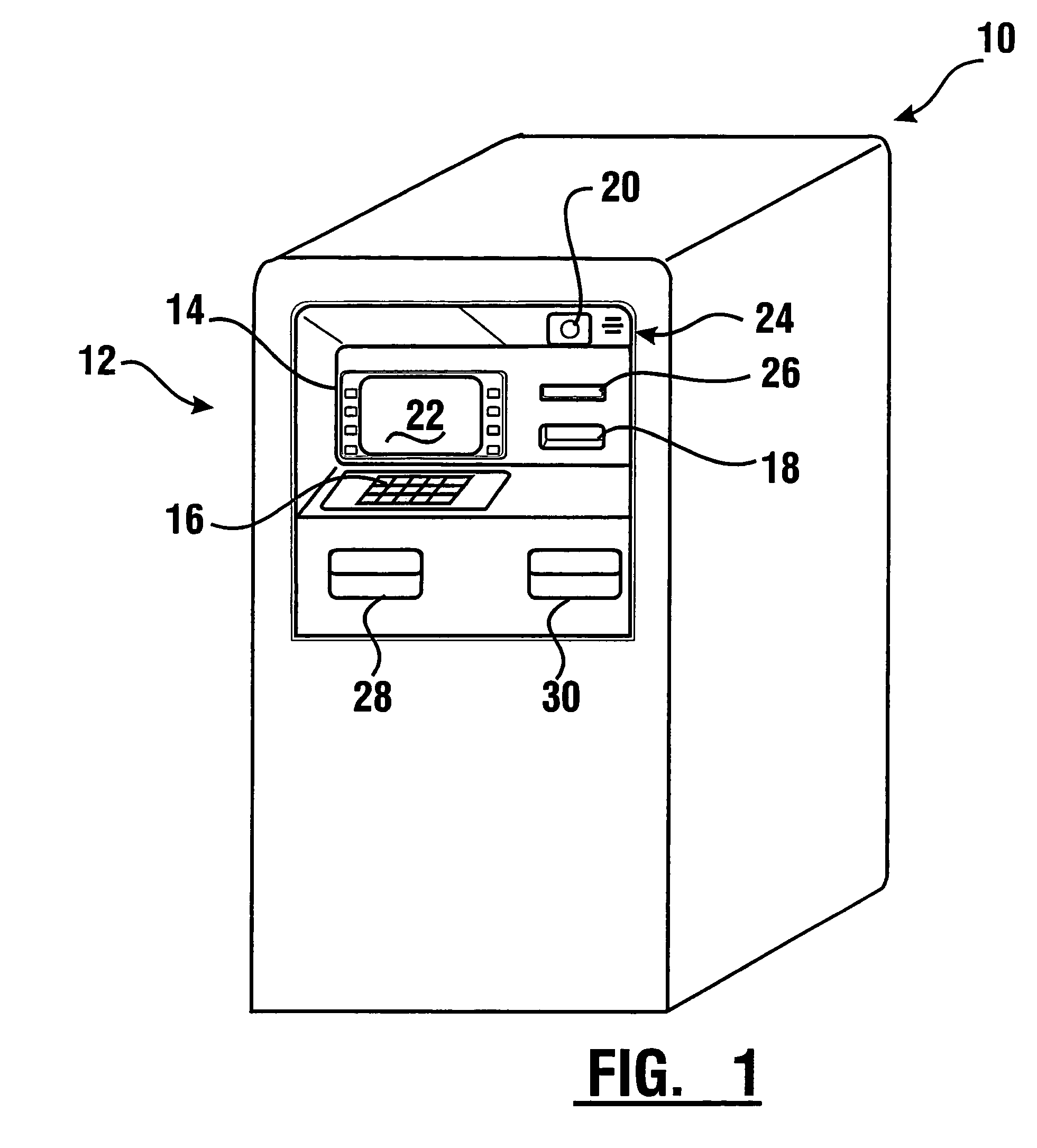
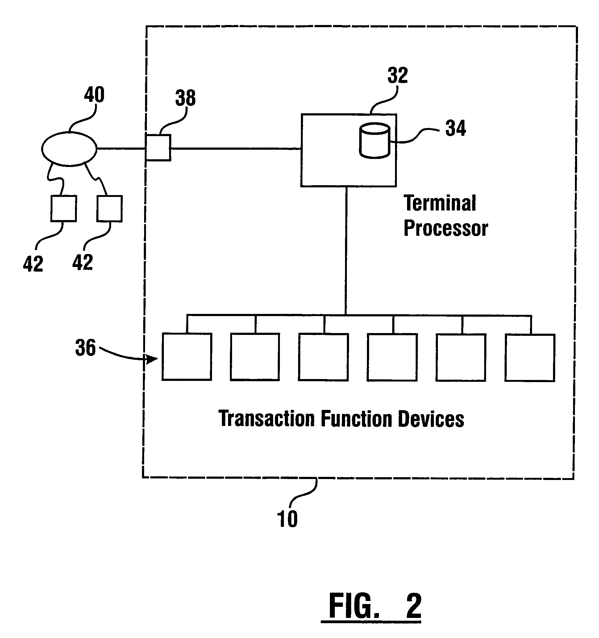
[0129]Referring now to the drawings and particularly to FIG. 1 and referring to U.S. Pat. No. 6,554,185, which is hereby incorporated herein by reference, there is shown therein an example embodiment of an automated banking machine 10 which includes an example deposit accepting apparatus and which performs at least one operation. Automated banking machine 10 is an ATM. However it should be understood that the inventive concepts disclosed herein may be used in connection with various types of automated banking machines and devices of other types. Automated banking machine 10 includes a user interface generally indicated 12. User interface 12 includes input and output devices. In the example embodiment the input devices include a plurality of function buttons 14 through which a user may provide inputs to the machine. The example input devices further include a keypad 16 through which a user may provide numeric or other inputs. A further input device in this example embodiment includes...


PUM


Abstract

An automated banking machine system and method includes ATMs which accept checks and dispense cash to users. The ATMs are operated to acquire image and magnetic data from deposited checks to determine the genuineness of checks and the authority of a user to receive cash for such checks. Cash may be dispensed to the user from the ATM in exchange for the deposited check. The ATMs dispense cash responsive to communications with a transaction host. The transaction host provides transaction identifying data to the ATM. The ATM sends the transaction identifying data and check images to an image and transaction data server for processing.

Description

CROSS REFERENCE TO RELATED APPLICATIONS[0001]This application claims benefit pursuant to 35 U.S.C. § 119(e) of Provisional Application No. 60 / 660,075 filed Mar. 9, 2005 and Provisional Application No. 60 / 659,990 filed Mar. 9, 2005. This Application is also a Continuation-In-Part Application pursuant to 35 U.S.C. § 120 of co-pending application Ser. No. 10 / 944,578 filed Sep. 16, 2004 which claims benefit pursuant to 35 U.S.C. § 119(e) of Provisional Application No. 60 / 504,776 filed Sep. 17, 2003; Provisional Application No. 60 / 504,282 filed Sep. 17, 2003; Provisional Application No. 60 / 503,825 filed Sep. 22, 2003; Provisional Application No. 60 / 537,581 filed Jan. 20, 2004; Provisional Application No. 60 / 537,795 filed Jan. 20, 2004; Provisional application No. 60 / 537,788 filed Jan. 20, 2004; and Provisional Application No. 60 / 584,622 filed Jun. 29, 2004. Application Ser. No. 10 / 944,578 is a Continuation-In-Part Application pursuant to 35 U.S.C. § 120 of co-pending application Ser. No....

Claims


Application Information

Patent Timeline
IPC IPC(8): G06Q40/00
CPCG06Q20/042G06Q40/02G07D7/04G07D7/12G07D7/2058G07F19/20G07F19/202G07F19/205G07D7/181G07D7/183G07D7/206
Inventor CARPENTER, KEITHRYAN, MIKECREWS, TIMPATHAK, RAHULMA, SONGTAOLASKOWSKI, EDWARD L.
Owner DIEBOLD SELF SERVICE SYST DIV OF DIEBOLD NIXDORF INC
Learn More