
Optical sensor, optical temperature-measuring device and measuring method using the optical sensor

a technology of optical sensors and temperature-measuring devices, which is applied in the direction of optical radiation measurement, heat measurement, instruments, etc., can solve the problem of difficult low-cost supply of circuits, and achieve the effect of enhanced low-cost and excellent

Inactive Publication Date: 2009-02-24
HITACHI CABLE
View PDF12 Cites 11 Cited by
  • Summary
  • Abstract
  • Description
  • Claims
  • Application Information

AI Technical Summary

Benefits of technology

[0020]Accordingly, it is an object of the invention to provide an optical sensor, an optical temperature-measuring device and a measuring method using the optical sensor that are capable of enhancing the axial resolution of the temperature measurement at a low cost without increasing the sampling frequency or narrowing the pulse width.

Problems solved by technology

However, such a circuit is difficult to provide at a low cost based on the present technology level.

Method used


Image

  • Optical sensor, optical temperature-measuring device and measuring method using the optical sensor
  • Optical sensor, optical temperature-measuring device and measuring method using the optical sensor
  • Optical sensor, optical temperature-measuring device and measuring method using the optical sensor

Examples


Embodiment Construction

[0072]Preferred embodiment according to this invention will be explained in more detailed in conjunction with the appended drawings.

[0073]Although the invention relates to an optical sensor to measure temperature, distortion, and pressure or to detect the breaking portion of long cables etc., in this embodiment, an optical temperature sensor to measure temperature will be described below.

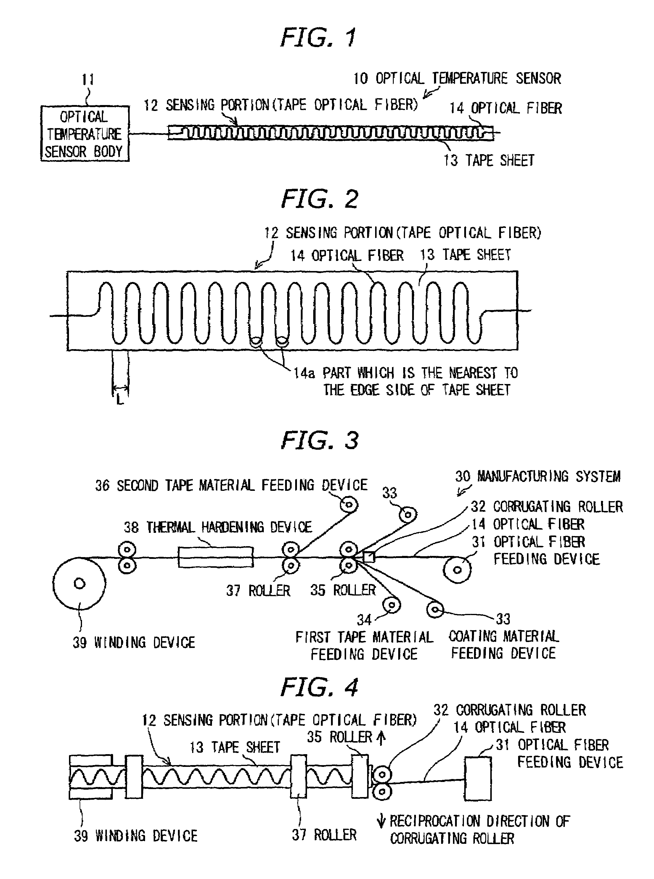
[0074]FIG. 1 is a plan view of the optical temperature sensor in the preferred embodiment according to the invention.

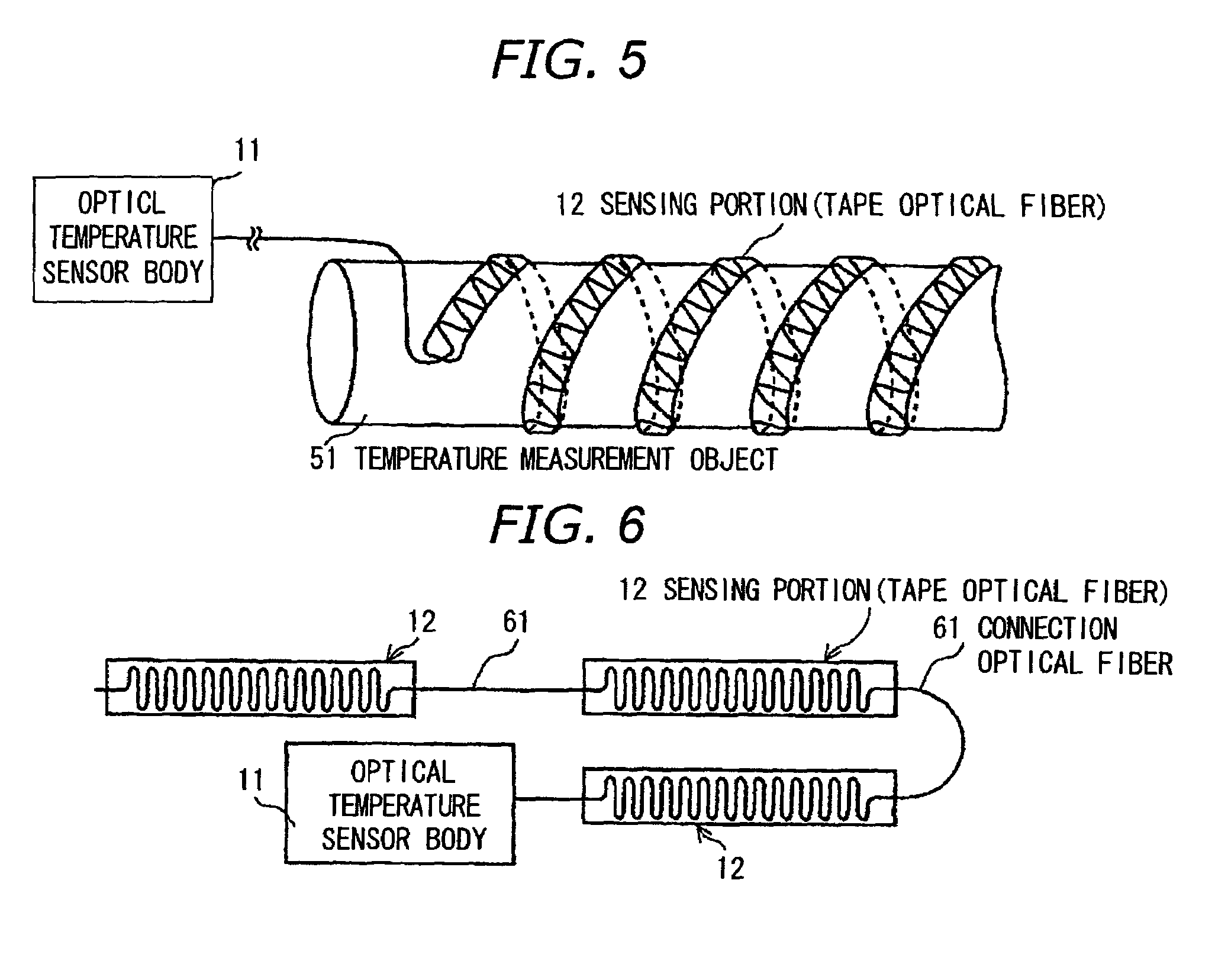
[0075]The optical temperature sensor 10 comprises a temperature sensor body 11 and a sensing portion 12 with an optical fiber 14 disposed at a measurement point for temperature. The temperature sensor body 11 comprises mainly a light source to output a light to the sensing portion 12 and a photodetector to detect a Raman scattering light from the sensing portion 12. However, the connection among the light source, the photodetector and the optical fiber 14 is made similarly to the opti...


PUM

PropertyMeasurementUnit
diameteraaaaaaaaaa
lengthaaaaaaaaaa
lengthaaaaaaaaaa

Abstract

An optical sensor has: a sensing portion having an optical fiber to be disposed at a measurement point of temperature, distortion, pressure etc.; a light source to output a light to the sensing portion; and a photodetector to detect a backscattered light from the sensing portion. The sensing portion has a tape sheet and the optical fiber shaped into a corrugated form with a predetermined curvature. Alternatively, the sensing portion has a polymer optical waveguide with a core shaped into a corrugated form with a predetermined curvature.

Description

[0001]The present application is based on Japanese patent application No. 2005-379100 filed on Dec. 28, 2005, the entire contents of which are incorporated herein by reference.BACKGROUND OF THE INVENTION[0002]1. Field of the Invention[0003]This invention relates to an optical sensor, an optical temperature-measuring device and a measuring method using the optical sensor, which are capable of measuring temperature etc. by detecting Raman scattering light which is generated in an optical fiber etc.[0004]2. Description of the Related Art[0005]An optical sensor is known that measures temperature, distortion, and pressure, or detects breaking portion by using an optical fiber etc. Particularly, an optical temperature sensor using Raman scattering of the optical fiber is known.[0006]FIG. 7 is a circuit diagram showing an optical temperature-measuring device 70 composed by connecting an electric circuit 72 to an optical temperature sensor 71.[0007]As shown in FIG. 7, the optical temperatur...

Claims


Application Information

Patent Timeline
Patent Type & Authority Patents(United States)
IPC IPC(8): H01J40/00G01J1/04G02B6/00H01S3/00
CPCG01J1/04G01J1/0425G01J5/08G01J5/0821G01J5/0846G01J5/0862G01J5/0896G01J5/602G01K11/32G01L11/025G01J5/0802
Inventor OGURA, MASAKIKOBAYASHI, MASAHIKOHIRUTA, AKIHIRO
Owner HITACHI CABLE
Learn More