Ultrasonic transducer, acoustic impedance matching layer and preparation method of acoustic impedance matching layer

A technology of ultrasonic transducers and matching layers, which is applied in the direction of sound-emitting devices, instruments, and fluids using vibrations, etc., can solve the problems of increased processing technology difficulty, energy loss, and small thickness of matching layers, etc., to achieve improved axial resolution and information richness, improve transmission efficiency, and reduce the effect of pulse width

Active Publication Date: 2019-09-24
聚融医疗科技(杭州)有限公司
View PDF7 Cites 5 Cited by
  • Summary
  • Abstract
  • Description
  • Claims
  • Application Information

AI Technical Summary

Problems solved by technology

[0004] 1) There is still an impedance mismatch between the matching layers, resulting in energy loss;
[0005] 2) Since the transmitted wave is a pulse wave, which contains a variety of frequency components, the wavelength difference in the matching layer is large, and the theoretical thickness calculated according to λ / 4 is also different. The thickness of the matching layer with a fixed thickness will inevitably lead to Acoustic waves with different frequency components produce different losses in the matching layer, causing signal integrity problems;
[0006] 3) The frequency of the high-frequency ultrasonic transducer is high, and the thickness of the matching layer calculated according to the λ / 4 theory is small, the processing technology is more difficult, and the precision is difficult to control
[0007] The best way to solve the above problems is to prepare matching layer materials with gradual impedance changes. However, according to the relevant patents published at present, some matching layer materials are difficult to prepare or cannot be obtained with continuous and uniform impedance changes. More importantly, matching layer materials The thickness of the layer cannot be precisely controlled, which makes the preparation of later products more difficult (such as array element cutting, etc.)

Method used


Image

  • Ultrasonic transducer, acoustic impedance matching layer and preparation method of acoustic impedance matching layer
  • Ultrasonic transducer, acoustic impedance matching layer and preparation method of acoustic impedance matching layer
  • Ultrasonic transducer, acoustic impedance matching layer and preparation method of acoustic impedance matching layer

Examples


preparation example Construction

[0043]

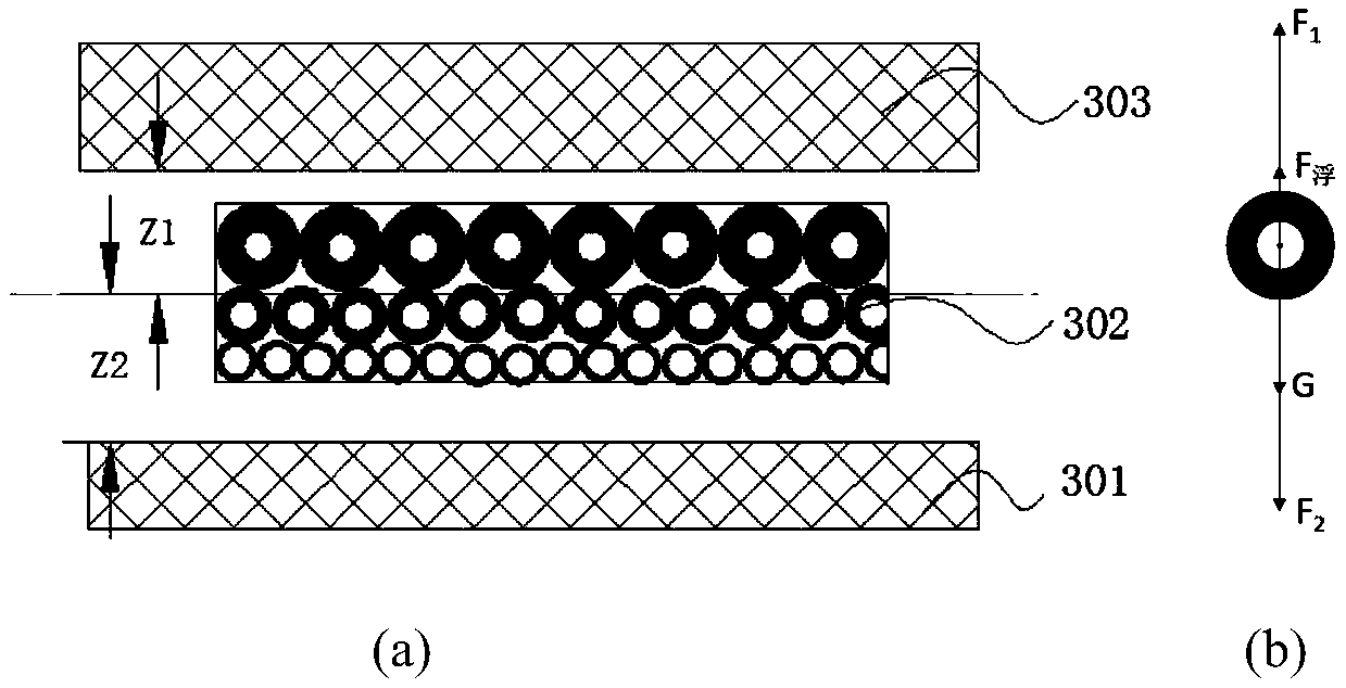
[0044] The present invention also provides a method for preparing an acoustic impedance matching layer, comprising the following steps: screening the magnetic particles, and coating the surface of the magnetic particles with a low-density material, so that the particle size of the magnetic particles or the thickness of the low-density material is gradient Distribution: Disperse the obtained magnetic particles coated with low-density materials in a container filled with liquid adhesive, apply a magnetic field to the container from top to bottom, and keep it for a certain period of time, so that the magnetic particles in the container are stable Distributed in the liquid adhesive; solidify the material in the container, take out the cured material, and grind both sides to obtain the acoustic impedance matching layer.

[0045] The screening of magnetic particles can screen out magnetic particles with the same particle size, and then coat the particles by physical or che...

Embodiment 1

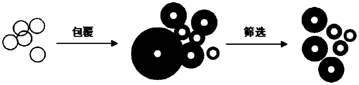
[0051] The method of screening first and then coating is used to prepare the magnetic filling particles.

[0052] like figure 2 As shown, the iron particles with a particle size of (10-15) μm are screened out through the upper and lower sieves, and the density is about 7g / cm 3 , The acoustic impedance is about 33MRayl. A layer of silicone rubber material is coated on its surface by in-situ polymerization method, and the density of the selected silicone rubber material is about 1g / cm 3 , the acoustic impedance is about 1MRayl. By controlling the reaction temperature and prolonging the reaction time, a layer of (0-120) μm thick coating layer is coated on the surface of iron micro-particles, and the density of the obtained composite particles varies in the range of about (1.1-7) g / cm 3 , through screening to obtain mixed particles with a gradient distribution of particle size (or density).

[0053] Use epoxy resin with low viscosity as the adhesive, such as EPOTEK 301, DER 3...

Embodiment 2

[0057] The method of screening first and then coating is used to prepare the magnetic filling particles.

[0058] like Figure 5 As shown, the magnetic particles with particle size gradient distribution are screened out by sieving or cyclone separation, and then the conditions are precisely controlled, and the particle surface is coated in equal amounts by physical or chemical methods such as sputtering, vapor deposition, in-situ polymerization, and rotary evaporation. A layer of low-density material is covered, because the particle size of the uncoated particles presents a gradient distribution, so the density of the coated composite material also presents a gradient distribution, that is, the stress presents a gradient distribution. Then, the matching layer material 601 with a gradient distribution of acoustic impedance is obtained by designing with the same principle as in Embodiment 1, as Image 6 shown.


PUM


Abstract

The invention discloses an ultrasonic transducer, an acoustic impedance matching layer and a preparation method of the acoustic impedance matching layer. The acoustic impedance matching layer comprises magnetic particles coated with a low-density material layer and an adhesive, wherein the magnetic particles coated with the low-density material are in graded distribution in the adhesive based on different acoustic impedance, such that the acoustic impedance of the acoustic impedance matching layer are in gradient distribution from one end to the other end. The preparation method of the acoustic impedance matching layer is appropriate in difficulty. Operation equipment is simple. The prepared acoustic impedance matching layer is in uniform gradient variation of acoustic impedance, has an accurately controllable thickness, can improve the transmission efficiency of acoustic waves in the ultrasonic transducer and improves the sensitivity and the bandwidth of the ultrasonic transducer.

Description

technical field [0001] The invention belongs to the technical field of ultrasonic transducers, in particular to an ultrasonic transducer, an acoustic impedance matching layer and a preparation method thereof. Background technique [0002] In biomedical ultrasound engineering, a large amount of acoustic energy is lost due to impedance mismatch between the piezoelectric layer with high acoustic impedance (about 30 MRayl) and the working medium with low acoustic impedance (about 1.5 MRayl). In addition, the significant difference in impedance will also cause the piezoelectric element to resonate with a high Q value, resulting in longer pulse width and narrower bandwidth, which seriously affects the sensitivity, axial resolution and information richness of the ultrasonic transducer. In order to solve this problem, the method of installing a matching layer between the piezoelectric layer and the working medium is often used for product preparation. In order to ensure the matchin...

Claims


Application Information

Patent Timeline
Patent Type & Authority Applications(China)
IPC IPC(8): B06B1/06G10K11/165
CPCB06B1/06G10K11/165
Inventor 任福杰鹿祥鹏徐璐杨东升
Owner 聚融医疗科技(杭州)有限公司
Why Eureka
Try Eureka