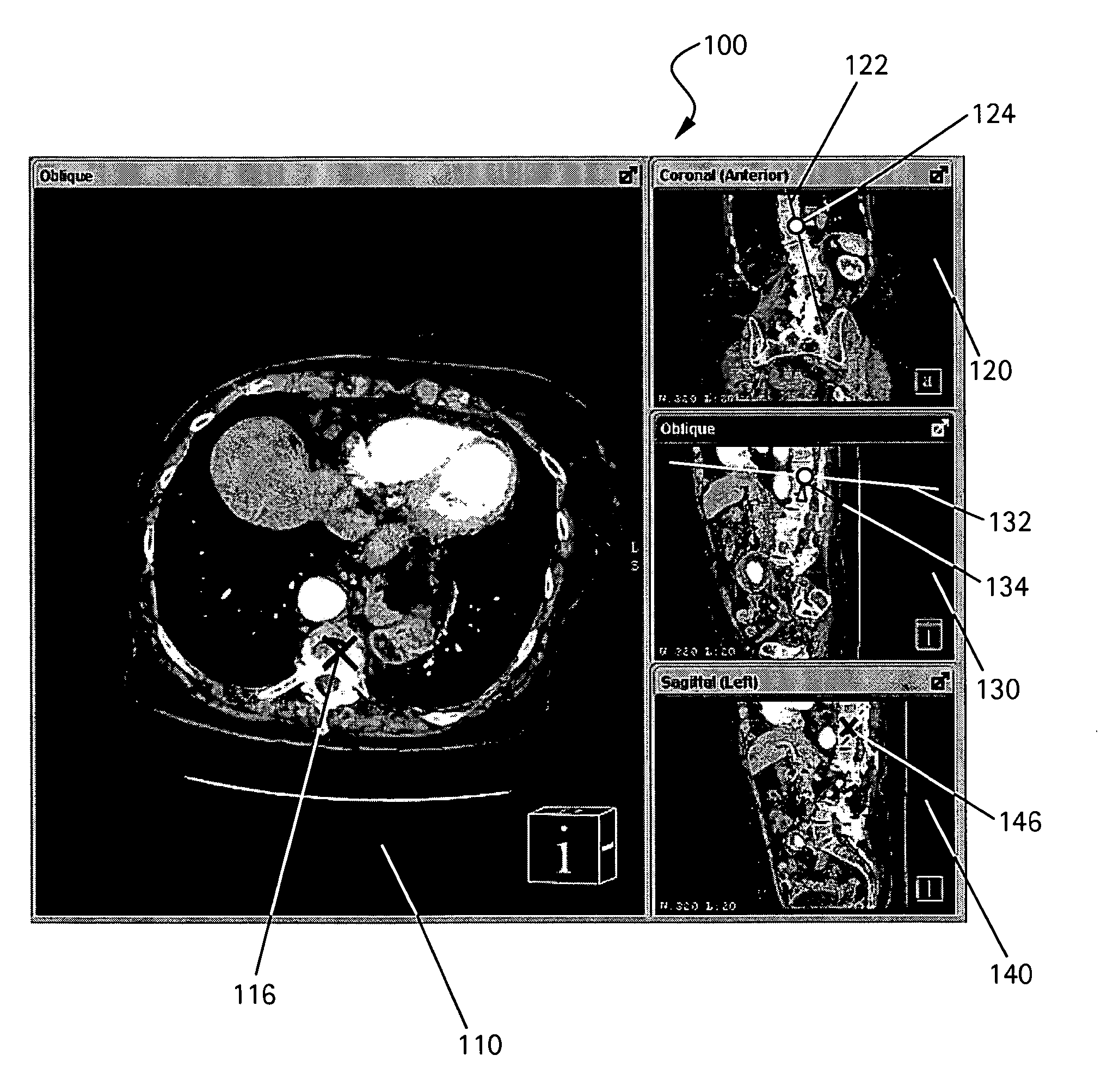

Method to define the 3D oblique cross-section of anatomy at a specific angle and be able to easily modify multiple angles of display simultaneously

a technology of defining a specific angle and defining a three-dimensional oblique cross-section, which is applied in the field of viewing medical images at several angles, can solve the problems of preventing the display of users are unable to move multiple control lines in multiple 2d images, and cannot witness multiple steps of the double oblique process simultaneously, so as to facilitate the modification facilitate the effect of multiple angles of display

Inactive Publication Date: 2009-02-24
GENERAL ELECTRIC CO
View PDF7 Cites 27 Cited by
  • Summary
  • Abstract
  • Description
  • Claims
  • Application Information

AI Technical Summary

Problems solved by technology

However, while current systems may display more than a single 2D image at a time, these systems typically display only a single step of the double oblique process.
Current systems do not include multiple control lines in multiple images, thereby prohibiting the display of multiple steps of the double oblique process.
Therefore, users are unable to move multiple control lines in multiple 2D images and are therefore unable to witness multiple steps of the double oblique process simultaneously.
Thus, current systems and methods do not allow the easy manipulation of the angle of display or the angle of cross-section in multiple cross-sectional images or cross-sectional stacks of images of a 3D volume in multiple viewports or displays.
For example, when attempting to view a specific portion of an anatomy in a medical image in 3D Maximum Intensity Pixel (“MIP”) / Multi-Planar Reformat (“MPR”) mode, free rotation, or rotation about a single line cannot always position the desired anatomy correctly in one or more of the subsequent viewports.
As described above, a major drawback of the existing methods is that the user can only see one prescribed cross-sectional view at a time.
As a result, if the user cannot obtain the view through the disk correctly, the user may need to go back to the first step to adjust the pseudo-sagittal view from the coronal image.
However, the user will no longer be able to see if the adjustments made are correct on the final image.
This will typically result in multiple iterations before a correct view through the disk can be obtained.
The above example shows that the existing oblique cross-sectioning methods are oftentimes time-consuming when used to obtain a view through multiple cross-sections.

Method used


Image

  • Method to define the 3D oblique cross-section of anatomy at a specific angle and be able to easily modify multiple angles of display simultaneously
  • Method to define the 3D oblique cross-section of anatomy at a specific angle and be able to easily modify multiple angles of display simultaneously
  • Method to define the 3D oblique cross-section of anatomy at a specific angle and be able to easily modify multiple angles of display simultaneously

Examples


Embodiment Construction

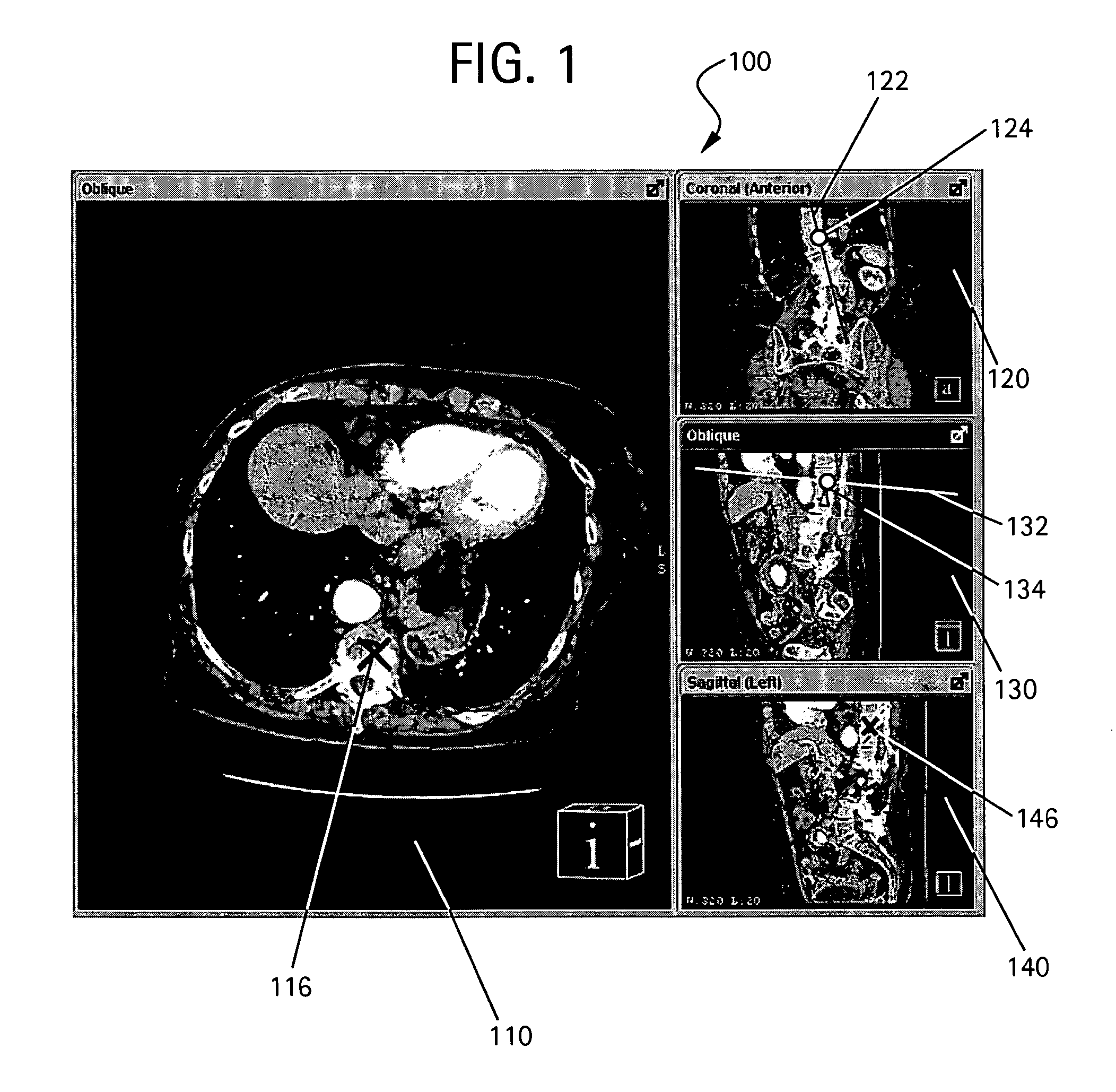
[0024]FIG. 5 illustrates a system 600 for simultaneously modifying one or more angles of display or angles of cross-section in one or more cross-sectional images or cross-sectional stack of images of a 3D volume according to an embodiment of the present invention. System 600 includes a computing device 610 and a computer-readable storage medium 620. Computing device 610 may include any one or more interconnected machines capable of carrying out operations based on one or more set of instructions. While a personal computer is shown as device 610 in FIG. 5, the various embodiments of the present invention are not limited to a personal computer. Any one or more interconnected machines capable of carrying out operations based on one or more set of instructions may comprise device 610. A set of instructions may include, for example, a software application or program, for example. Medium 620 may include any computer-readable storage medium, such as a local and / or remote memory. For exampl...


PUM


Abstract

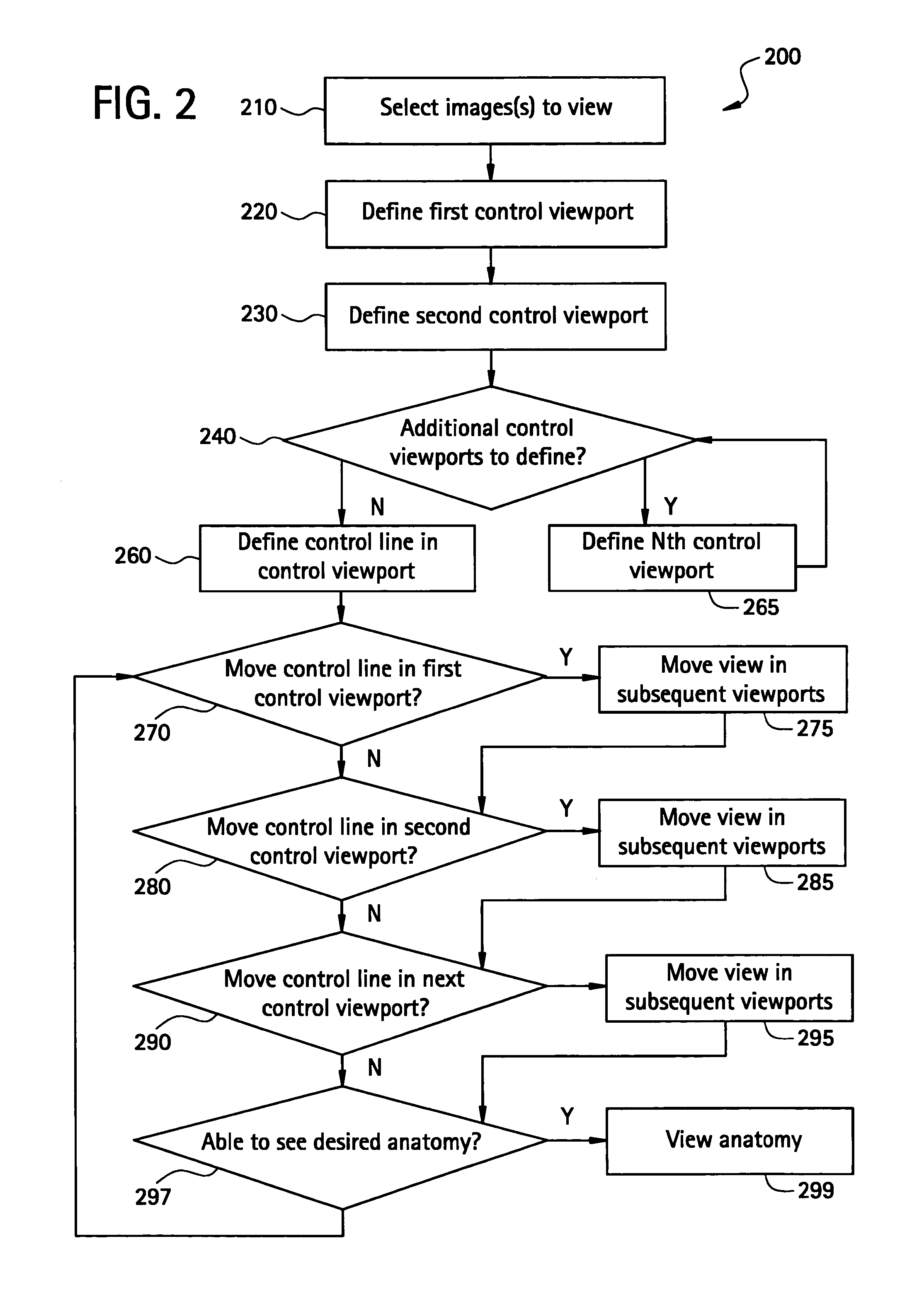
The present invention provides a system and a method for simultaneously modifying one or more angles of cross-sections in one or more cross-sectional images or stacks of images of a 3D volume. A plurality of viewports is displayed to a user. Each viewport includes a 2D cross-sectional image or stack of images and all 2D images or stacks of images are displayed simultaneously. One or more viewports may also include a control line representative of an angle of cross-section or image plane of a 2D image or stack of images displayed in another viewport. If a control line is moved in a selected viewport, the angle of cross-section or image plane of a 2D image or stack of images in another viewport is accordingly altered simultaneous with such control line movement.

Description

RELATED APPLICATIONS[0001]This application claims the benefit of U.S. Provisional Application No. 60 / 695,327, filed Jun. 23, 2005, entitled “A Method to Define the 3D Oblique Cross-Section of Anatomy at a Specific Angle and be Able to Easily Modify Multiple Angles of Display Simultaneously.” The disclosure of the '327 application is hereby incorporated by reference in its entirety.FEDERALLY SPONSORED RESEARCH OR DEVELOPMENT[0002]Not applicable.BACKGROUND OF THE INVENTION[0003]The present invention generally relates to the viewing of medical images at several angles. More specifically, the present invention relates to defining a three-dimensional (“3D”) oblique cross-section of an anatomy at a specific angle and to modify additional angles of display simultaneously.[0004]Current systems and methods allow for the viewing of a 3D volume of an object, such as a patient's anatomy, in one or more two-dimensional (“2D”) cross-sectional images or cross-sectional stack of images of the 3D vo...

Claims


Application Information

Patent Timeline
Patent Type & Authority Patents(United States)
IPC IPC(8): G06K9/00G06F17/00G06T1/00
CPCA61B6/032A61B6/463A61B6/465A61B6/466A61B6/5223G06T19/00G06T2219/008G06T2219/028
Inventor MUSSACK, CHRISTOPHER JOSEPHYAN, LITAOJONES, CHERYL RUTHMACK, DAVID CHARLES
Owner GENERAL ELECTRIC CO
Learn More