Stowable plant protector

a plant protector and stowable technology, applied in the field of plant protection, can solve the problems of destroying and even killing vegetation, burlap plant wrappings, and not being particularly attractive to passersby,

Inactive Publication Date: 2009-03-03
BAKOWSKI STEVEN M
View PDF38 Cites 36 Cited by
  • Summary
  • Abstract
  • Description
  • Claims
  • Application Information

AI Technical Summary

Problems solved by technology

By way of background, plants such as shrubs, young trees, ornamental plants and the like are often exposed during winter months to harsh environmental conditions that can damage and even kill the vegetation.
Although this technique represents an effective solution to plant protection, there are several drawbacks, including (1) the need to dispose of the burlap at the end of the season (due to rotting and UV degradation), (2) the difficulty associated with cutting the burlap to size, wrapping the plant, and then securing the covering with string or twine, (3) the care required to avoid wrapping the burlap too tightly or too loosely, the former giving rise to heat generation and desiccation of living foliage, the latter allowing burlap to unravel in high winds or permit foraging deer to pull off the burlap, and (4) the need to wrap exposed trunk areas in order to protect against road salt for plants situated next to roadways and walkways.
Burlap plant wrappings, moreover, are not particularly attractive to passersby.

Method used


Image

  • Stowable plant protector
  • Stowable plant protector
  • Stowable plant protector

Examples


Embodiment Construction

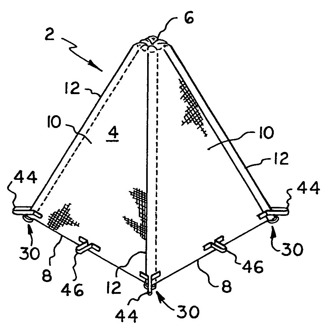
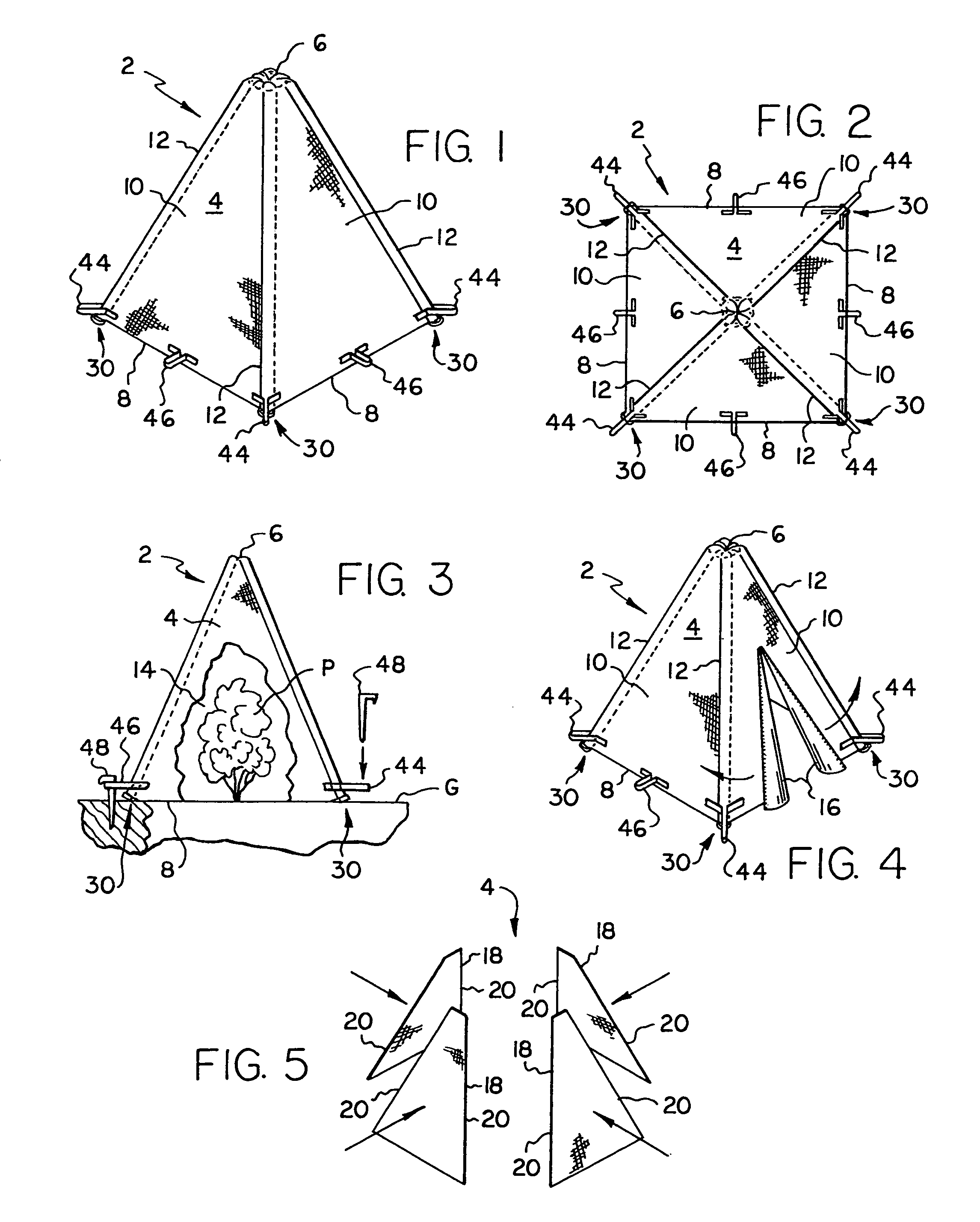
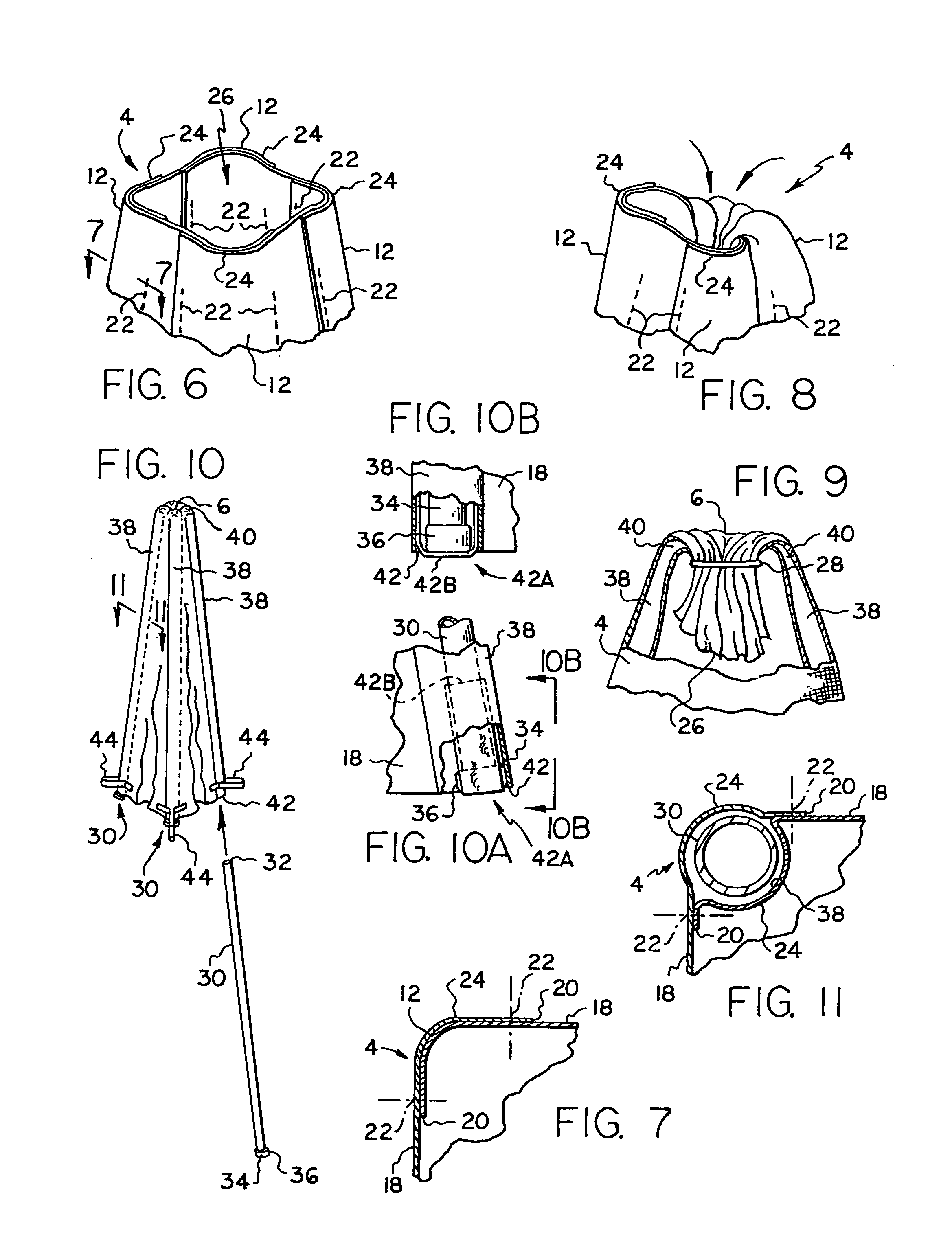
[0033]Turning now to the Drawings, wherein like reference numerals signify like elements in all of the several views, FIGS. 1-3 illustrate a plant protector 2 constructed in accordance with a first exemplary embodiment of the invention. The plant protector 2 includes a cover 4 formed from a flexible material sheet that is preferably air permeable and light transmissive. High density polyethylene fabric (HDPE) is one material that may be used to construct the cover 4. Polypropylene fabric is another material that may be used. The cover 4 may have any suitable transmissivity level, depending on prevailing climate conditions and the plant species to be protected. By way of example only, an HDPE fabric sold under the name “SHADE RITE” is available from Green-Tek, Inc. of Edgerton, Wis. (www.green-tek.com) with shade factors ranging from 30% to 90%. Another shade fabric available from Green-Tek, Inc. is sold under the name “ALUMINET.” This material comprises HDPE with a metalized coating...


PUM


Abstract

A plant protector includes a flexible cover having an apex, a base, plural sides and plural vertices defining intersections between adjacent sides, together with plural elongated frame members each respectively attached to the cover at one of the vertices. The frame members each have a first end proximate to the cover apex and a second end proximate to the cover base. The frame member first ends are mutually interconnected for pivoting at or below the cover apex. The pivotal interconnection may be provided by hinge connector hardware, but is more preferably provided by the cover itself functioning as a living hinge. The frame members are pivotable from an open position wherein the frame members are angled relative to each other to a collapsed position wherein the frame members are substantially parallel to each other. The plant protector has a deployment configuration wherein the frame members are in the open position members and the cover base is substantially open to define a plant-receiving interior region. The plant protector also has a stowage configuration wherein the frame members are in the collapsed position and the cover base and the plant-receiving interior region are substantially closed. Plural connectors are provided for securing the plant protector to a surface.

Description

BACKGROUND OF THE INVENTION[0001]1. Field of the Invention[0002]The present invention relates generally to plant protection. More particularly, the invention concerns protective coverings for shrubs, small trees and other plant specimens.[0003]2. Description of Prior Art[0004]By way of background, plants such as shrubs, young trees, ornamental plants and the like are often exposed during winter months to harsh environmental conditions that can damage and even kill the vegetation. Typical injuries include limb breakage due to snow and ice loads, browning and die-back from frigid desiccating winds, bark girdling and leaf stripping caused by browsing deer, rabbits and mice, and frost damage. To counteract these effects, it is common practice to wrap sensitive species with a burlap covering in the fall, and thereafter remove the cover in the spring. Although this technique represents an effective solution to plant protection, there are several drawbacks, including (1) the need to dispos...

Claims


Application Information

Patent Timeline
Patent Type & Authority Patents(United States)
IPC IPC(8): A01G13/00A01G13/02E04H15/18
CPCA01G13/043
Inventor BAKOWSKI, STEVEN M.
Owner BAKOWSKI STEVEN M
Why Eureka
Try Eureka