Gas supply arrangement of a marine vessel and method of providing gas in a gas supply arrangement of a marine vessel

a gas supply arrangement and marine technology, applied in gas/liquid distribution and storage, auxiliaries, floating buildings, etc., can solve the problems of reducing the temperature of the reservoir, affecting the operation of the vessel, and the return of pumped liquid gas back, so as to reduce the effect of the temperature in the reservoir and the ease of maintaining desired temperatur

Inactive Publication Date: 2009-03-03
WARTSILA FINLAND OY
View PDF13 Cites 56 Cited by
  • Summary
  • Abstract
  • Description
  • Claims
  • Application Information

AI Technical Summary

Benefits of technology

[0015]The first duct section of the second gas supply line and the return line are preferably in heat transfer relation with each other by a first heat exchanger device so that the liquid gas from the cargo tank may be preheated and the returned gas cooled. The heat transfer relation makes it easier to maintain desired temperature in the reservoir. The gas reservoir is provided wi

Problems solved by technology

However, the amount of natural boil-off gas is not sufficient for providing all energy required in all circumstances and therefore the vessel must be provided with additional means for acquiring extra gas, so called forced boil-off gas.
It has, however, some problems, which are discussed below.
A problem in this arrangement is the returning of the pumped liquid gas back to the cargo tank.
That is not desired due to the heating effect of the liquid gas slig

Method used


Image

  • Gas supply arrangement of a marine vessel and method of providing gas in a gas supply arrangement of a marine vessel
  • Gas supply arrangement of a marine vessel and method of providing gas in a gas supply arrangement of a marine vessel
  • Gas supply arrangement of a marine vessel and method of providing gas in a gas supply arrangement of a marine vessel

Examples


Embodiment Construction

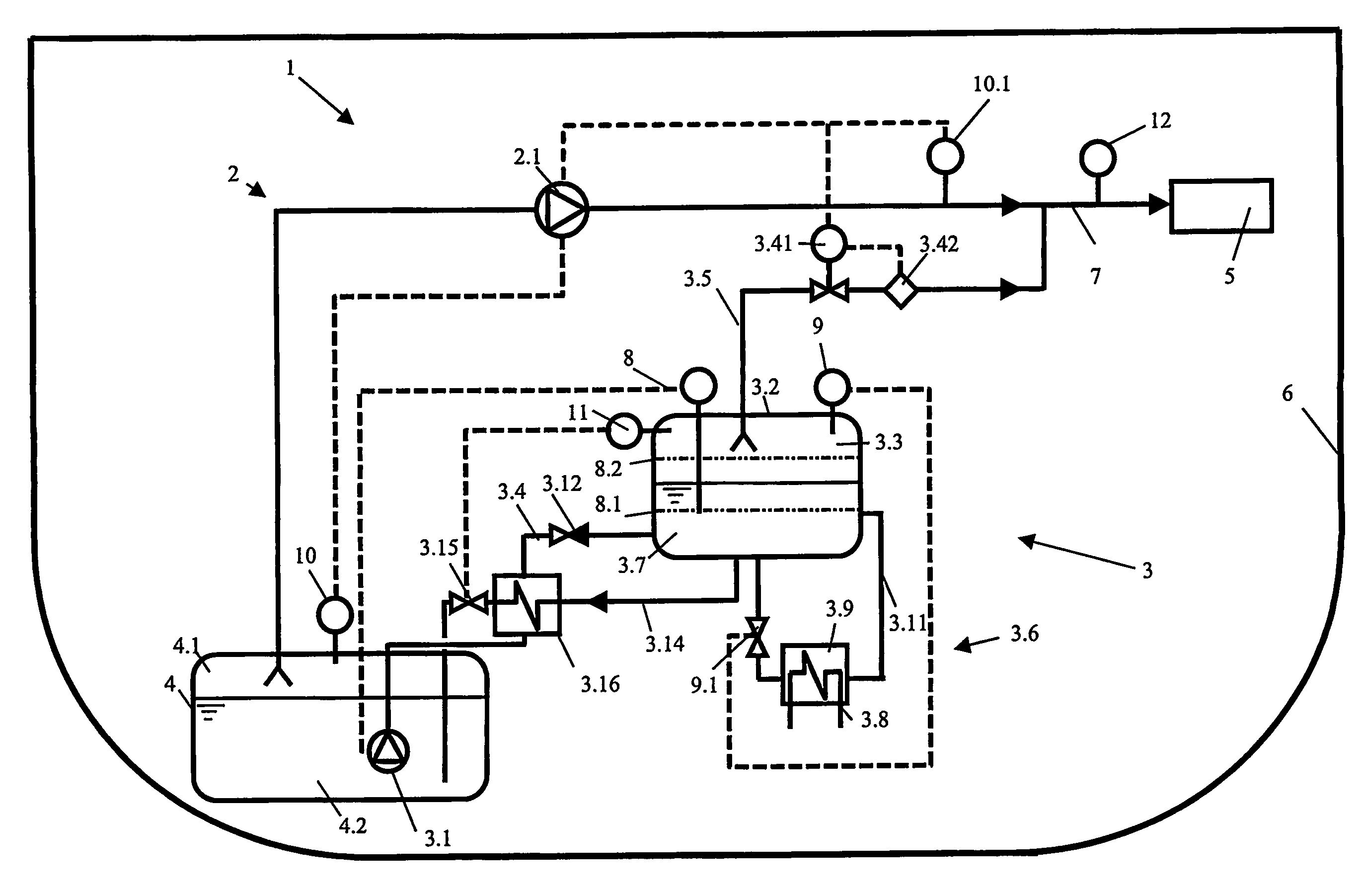
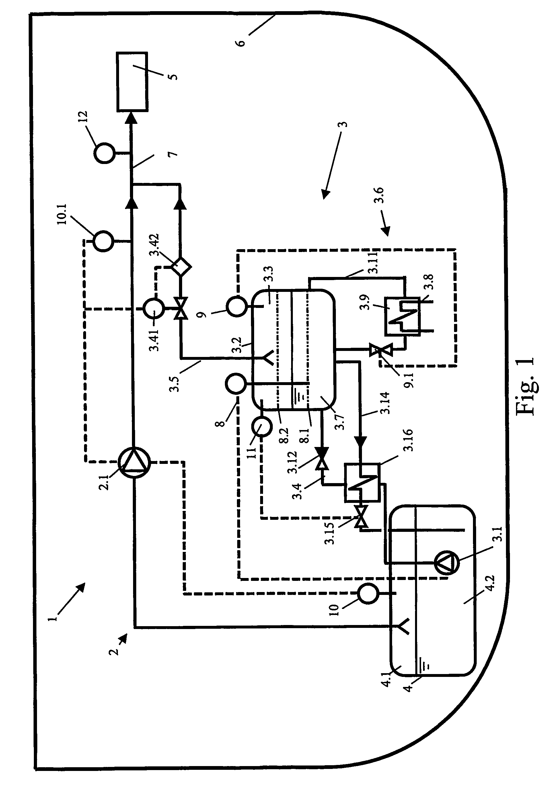
[0018]FIG. 1 depicts schematically cross section of a marine vessel 6, like LNG tanker. The vessel 6 is adapted to carry liquefied gas in its cargo tanks 4. Normally there are several tanks in LNG tanker, but in the figure only one tank 4 is shown for clarity reasons. The cargo tank 4 is filled so that there is always an ullage space section 4.1 filled with gas in gaseous form and a liquid phase section 4.2 filled with liquefied gas. During the storing of the liquefied gas the gas is evaporating changing its phase and transferring to the ullage space section 4.1. The evaporated gas, so called natural boil-off gas, may be utilized in a consumption device 5 of the vessel 6. The consumption device 5 is preferably a gas engine providing propulsion power. In the figure only one consumption device 5 is shown but it is clear that there may be several devices.

[0019]In this embodiment the vessel 6 is provided with a gas supply arrangement 1, which comprises a first gas supply line 2 and a se...


PUM


Abstract

A gas supply arrangement of a marine vessel being adapted to carry liquefied gas in its cargo tank having an ullage space section and a liquid phase section, which arrangement utilizes the gas as fuel to provide power for the vessel, the arrangement comprising a first gas supply line provided for processing the natural boil-off gas formed in the cargo tank, a second gas supply line which connects the cargo tank and the gas main supply line and which is provided with at least a pump for raising the pressure of the liquid gas and for pumping it forward. The second gas supply line is provided with a gas reservoir having an ullage space section and liquid phase section, and that the arrangement is provided with a first duct section of the second gas supply line connecting the liquid phase section of the cargo tank and the liquid phase section of the gas reservoir, and being provided with the pump, and that the arrangement is additionally provided with a return line connecting the liquid phase section of the reservoir and the cargo tank being provided with a control valve for controllable returning liquid gas back into the cargo tank.

Description

[0001]This is a national stage application filed under 35 U.S.C 371 based on International Application No. PCT / F12004 / 050019 filed Feb. 25, 2004, and claims priority under 35 U.S.C 119 of Finnish Patent Application No. 20031848 filed Dec. 18, 2003 and International Application No. PCT / FI2004 / 050009 filed Jan. 30, 2004.BACKGROUND OF THE INVENTION[0002]The invention relates to a gas supply arrangement of a marine vessel and to a method of controlling gas pressure in a gas supply arrangement of a marine vessel.[0003]The usage of gas as energy source in marine vessels is advantageous due to its efficient burning and low emissions. Usually gas is stored in liquefied form because of less space is required for the storage that way.[0004]The propulsion system of LNG (Liquefied Natural Gas) tankers is usually powered by making use of the cargo. Storing of the gas in the tanker is arranged by using heat insulated cargo tanks into which an ullage space section and a liquid phase section are fo...

Claims


Application Information

Patent Timeline
IPC IPC(8): F17C13/00B63H21/02B63J99/00F17C1/00F17C7/00F17C9/02
CPCB63J99/00F17C1/002F17C7/00Y02T70/5263F17C2201/052F17C2201/054F17C2203/03F17C2205/0323F17C2205/0335F17C2221/033F17C2223/0161F17C2223/033F17C2223/043F17C2223/047F17C2225/0123F17C2225/013F17C2225/0153F17C2225/033F17C2225/047F17C2227/0142F17C2227/0157F17C2227/0178F17C2227/0185F17C2227/0304F17C2227/0306F17C2227/0309F17C2227/0339F17C2227/039F17C2250/01F17C2250/032F17C2250/0404F17C2250/0408F17C2250/043F17C2250/0439F17C2250/0443F17C2250/0452F17C2250/0491F17C2250/0626F17C2250/0631F17C2250/0636F17C2250/072F17C2250/075F17C2250/077F17C2260/02F17C2260/026F17C2265/015F17C2265/037F17C2265/066F17C2270/0105B63J2099/003Y02T70/50B63B25/14
Inventor KARLSSON, SORENMAHLANEN, TIMO
Owner WARTSILA FINLAND OY
Why Eureka
Try Eureka