Drive circuit for an injector arrangement and a diagnostic method

a technology of injector arrangement and drive circuit, which is applied in the direction of electric control, instruments, machines/engines, etc., to achieve the effect of small open circuit toleran

Inactive Publication Date: 2009-03-03
DELPHI TECH HLDG S A R L
View PDF18 Cites 20 Cited by
  • Summary
  • Abstract
  • Description
  • Claims
  • Application Information

AI Technical Summary

Benefits of technology

[0018]The first threshold current may be equal to substantially zero amps. This has the benefit that in order to detect a stack terminal short circuit fault, it is not necessary to sense a reference current for comparison with the sensed current.
[0019]The sensed current may be at variance from the first threshold current if it differs from the first threshold current by more than a tolerance current. So, in the detection of a stack terminal short circuit fault, errors of current measurement and insignificant stray currents may be accounted for. Beneficially, the diagnostic means provides a signal where the fuel injector is unable to function satisfactorily. Accordingly, the open sensed current may be considered to be substantially the same as the first threshold current if it falls within an open circuit tolerance current either side of the first threshold current. Advantageously, the diagnostic means is thus able to detect an open circuit fault in the injector arrangement, even where there are small systematic errors in measuring the sensed current. Furthermore, the open circuit tolerance is very small.
[0021]The third signal may be indicative of a short circuit fault when the predicted voltage is the voltage difference between the bank connection and the known voltage level and when the first fuel injector and the second fuel injector are deselected from the drive circuit. This provides the benefit that the diagnostic means is capable of detecting a short circuit fault associated with the first fuel injector. Thus, it is possible to detect the short circuit fault without having to select the first fuel injector or the second fuel injector, restricting the damage that may be caused to the fuel injectors and the rest of the drive circuit by the short circuit fault.
[0025]In one embodiment, the drive circuit has a power supply means. In addition, the drive circuit may have a regeneration switch means. The operation of the regeneration switch means may transfer charge from the power supply means to the first charge storage means, before a subsequent discharge phase. Operating the regeneration switch means provides an advantage of enabling detection of a short circuit fault indicated by the fourth signal. The regeneration switch means may be operated prior to the detection of a fault and, advantageously, is operable at the end of the charging phase to transfer charge.

Problems solved by technology

However, if the fuel injector has a short circuit fault between terminals of the actuator (termed a “stack terminal short circuit fault”) the fuel injector conducts to discharge.
However, if the deselected fuel injector has a stack terminal short circuit fault, it draws current away from the selected capacitive component.

Method used


Image

  • Drive circuit for an injector arrangement and a diagnostic method
  • Drive circuit for an injector arrangement and a diagnostic method
  • Drive circuit for an injector arrangement and a diagnostic method

Examples


Embodiment Construction

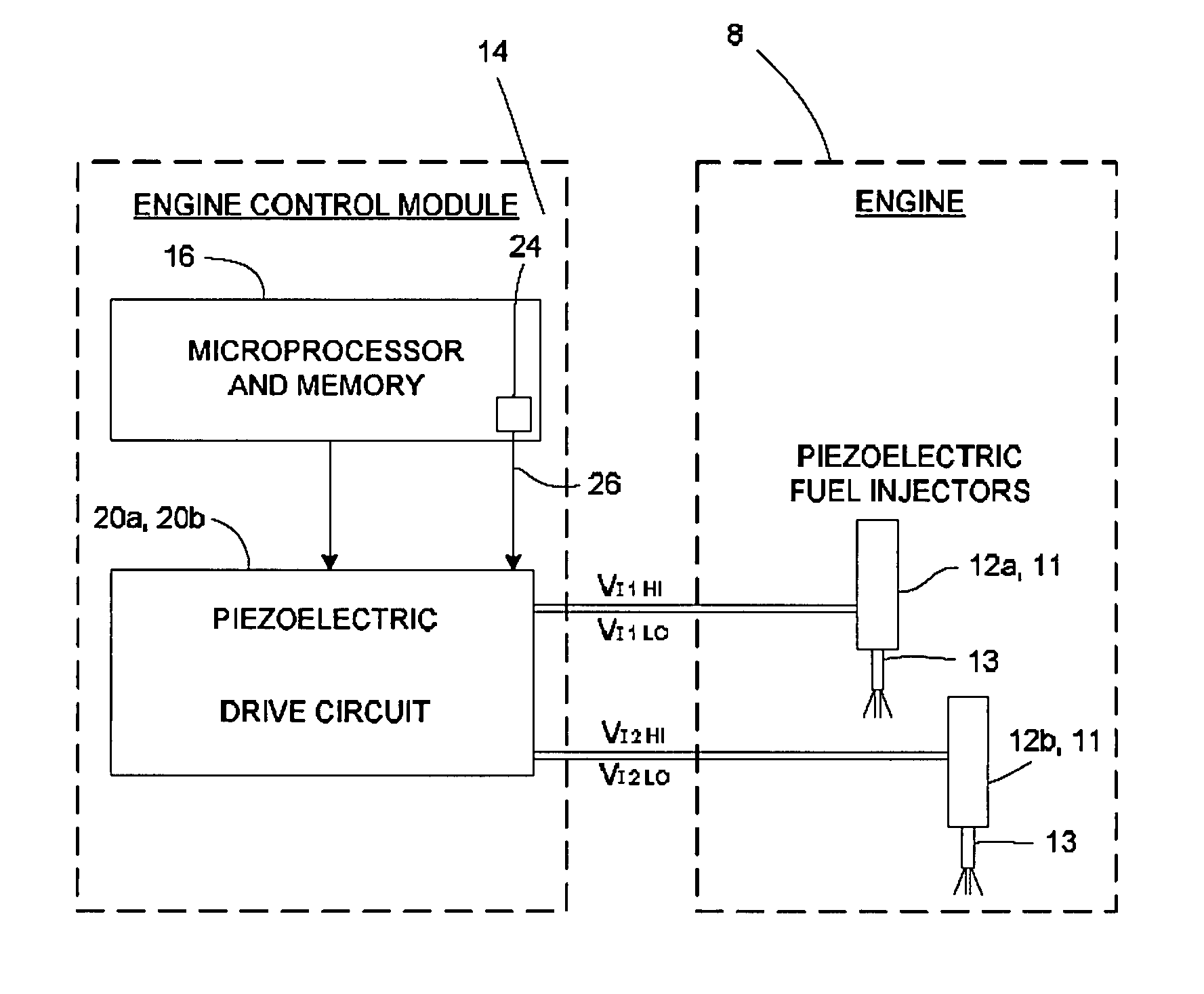
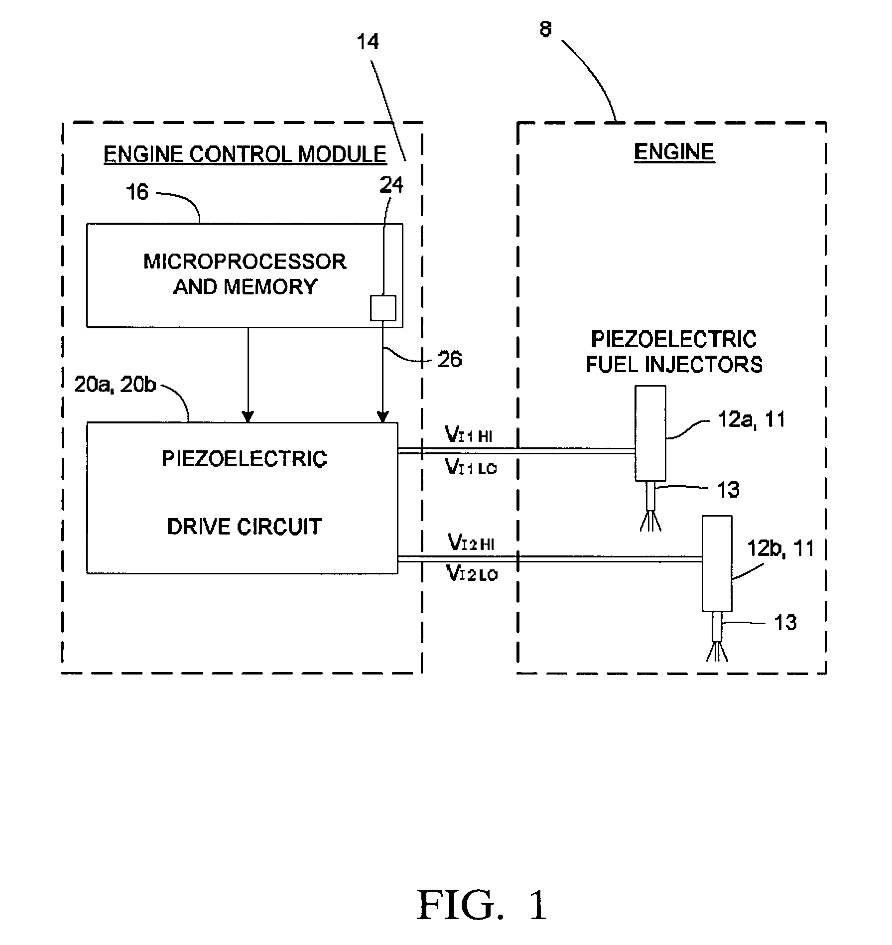
[0048]Referring to FIG. 1, an engine 8, such as an automotive vehicle engine, is generally shown having an injector arrangement comprising a first fuel injector 12a and a second fuel injector 12b. The fuel injectors 12a, 12b each have an injector valve needle 13 and a piezoelectric actuator 11. The piezoelectric actuator 11 is operable to cause the injector valve needle 13 to open and close to control the injection of fuel into an associated cylinder of the engine 8. The fuel injectors 12a, 12b may be employed in a diesel internal combustion engine to inject diesel fuel into the engine 8, or they may be employed in a spark ignited internal combustion engine to inject combustible gasoline into the engine 8.

[0049]The fuel injectors 12a, 12b form a first injector set 10 of fuel injectors of the engine 8 and are controlled by means of a drive circuit 20a. The drive circuit 20a is arranged to monitor and control the injector high side voltages VI1HI, VI2HI and injector low side voltages ...


PUM


Abstract

The invention relates to a drive circuit for an injector arrangement comprising a first fuel injector in parallel with a capacitive component. The drive circuit comprises: a selector means (SQ1, SQ2) and diagnostic means. The selector means (SQ1, SQ2) is operable to select the first fuel injector and / or the capacitive component into the drive circuit and to deselect the first fuel injector and / or the capacitive component from the drive circuit. When the capacitive component is selected and the first fuel injector is deselected, the diagnostic means is operable to sense a current (Isense) through the first fuel injector. When the sensed current (Isense) is at variance from a first threshold current (Ilimit) the diagnostic means is operable to provide a first signal on detection of a stack terminal short circuit fault associated with the first fuel injector. The capacitive component may be a second fuel injector.

Description

TECHNICAL FIELD[0001]The present invention relates to a drive circuit for an injector arrangement having a diagnostic means for detecting a fault, and to a diagnostic method for the drive circuit of an injector arrangement. The drive circuit is especially, although not exclusively, for an injector arrangement in an internal combustion engine, the injector arrangement including an injector of the type having a piezoelectric actuator for controlling injector valve needle movement.BACKGROUND ART[0002]Automotive vehicle engines are generally equipped with fuel injectors for injecting fuel (e.g., gasoline or diesel fuel) into the individual cylinders or intake manifold of the engine. The engine fuel injectors are coupled to a fuel rail which contains high pressure fuel that is delivered by way of a fuel delivery system. In diesel engines, conventional fuel injectors typically employ a valve needle that is actuated to open and to close in order to control the amount of fluid fuel metered ...

Claims


Application Information

Patent Timeline
Patent Type & Authority Patents(United States)
IPC IPC(8): F02M51/00
CPCF02D41/2096F02D41/221F02D2041/2048F02D2041/2058F02D2041/2093
Inventor PERRYMAN, LOUISA JSYKES, MARTIN A P
Owner DELPHI TECH HLDG S A R L
Why Eureka
Try Eureka