Device for separating impurities from the lubricating oil of an internal combustion engine

a technology for separating impurities and lubricating oil, which is applied in the direction of gravity filters, loose filtering material filters, centrifuges, etc., can solve the problems of contaminated lubricating oil easily being released into the environment, the locking connection cannot be undone, and the effort required to undo the locking connection is great, so as to achieve the effect of low weight, simple manufacture and mounting of the device, and low cost of bulk production

Inactive Publication Date: 2009-03-03
HENGST WALTER
View PDF14 Cites 7 Cited by
  • Summary
  • Abstract
  • Description
  • Claims
  • Application Information

AI Technical Summary

Benefits of technology

[0027]For the device, it is furthermore preferably provided that the screw cap, the upper end disk of the filter element as well as the intermediate cap if necessary and, if need be, the ring with the cam segments are each single-piece injection-molded parts of plastic. This permits cost-effective bulk production and results in a low weight of the device.
[

Problems solved by technology

In the case of screw caps which provide only little lateral motional play for the filter element partially arranged therein, this especially being the case with relatively long screw caps, it is not possible to undo the locking connection by canting because the deflection angle required between the two parts fails to be achieved since the filter element touches the internal perimeter of the screw cap beforehand.
In this case, great effort is required to undo the locking connection by exerting a tractive force in an axial direction.
To achieve this, the dirty filter element must be seized, and in this process, contaminated lubricating oil

Method used


Image

  • Device for separating impurities from the lubricating oil of an internal combustion engine
  • Device for separating impurities from the lubricating oil of an internal combustion engine
  • Device for separating impurities from the lubricating oil of an internal combustion engine

Examples


first embodiment

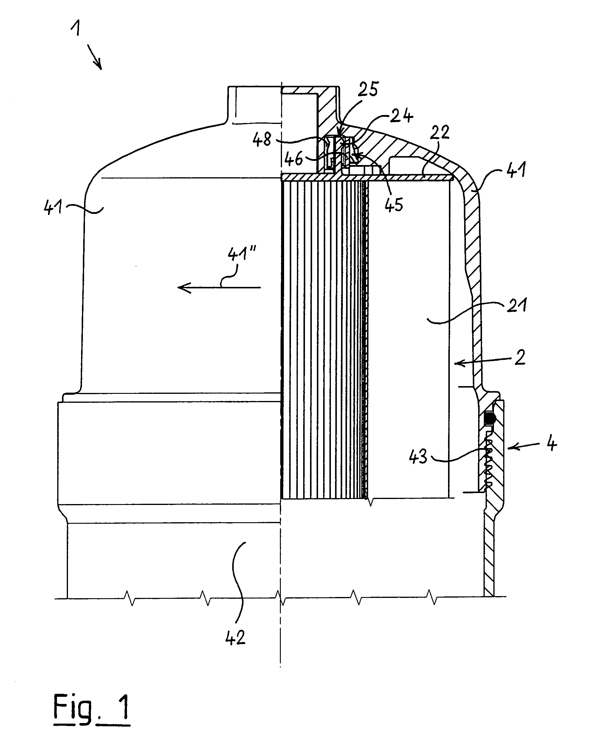
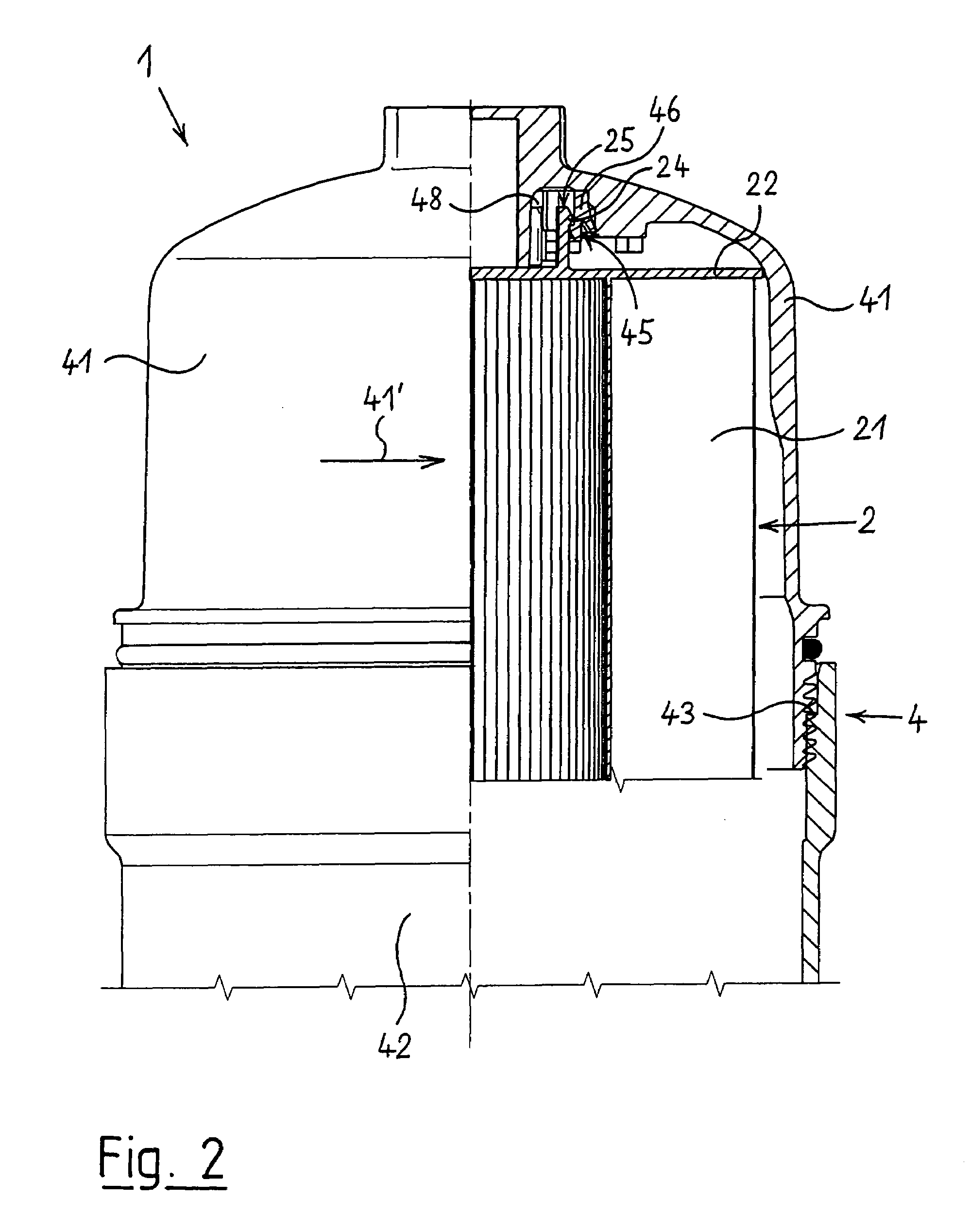
[0043]As shown in FIG. 1 of the drawing, the represented first embodiment of a device 1 for separating impurities from the lubricating oil of an internal combustion engine is designed as a pure filter. To this end, the device possesses a housing 4 that comprises a stationary lower housing part 42 and an upper screw cap 41 connected thereto in a detachable manner. In a lower part of the filter housing 4, which is not shown in FIG. 1, ducts, at least for supplying lubricating oil to be purified and for discharging purified lubricating oil, are provided in the usual manner.

[0044]The lower housing part 42 and the screw cap 41 can be connected to and separated from each other by means of a screw thread that is rotated. The arrow 41″ on the screw cap 41 indicates the tightening rotational direction of said screw cap 41.

[0045]In the state of the device 1 shown in FIG. 1, the screw cap 41 is securely screwed to the lower housing part 42 and is sealed by a gasket.

[0046]A filter element 2 tha...

second embodiment

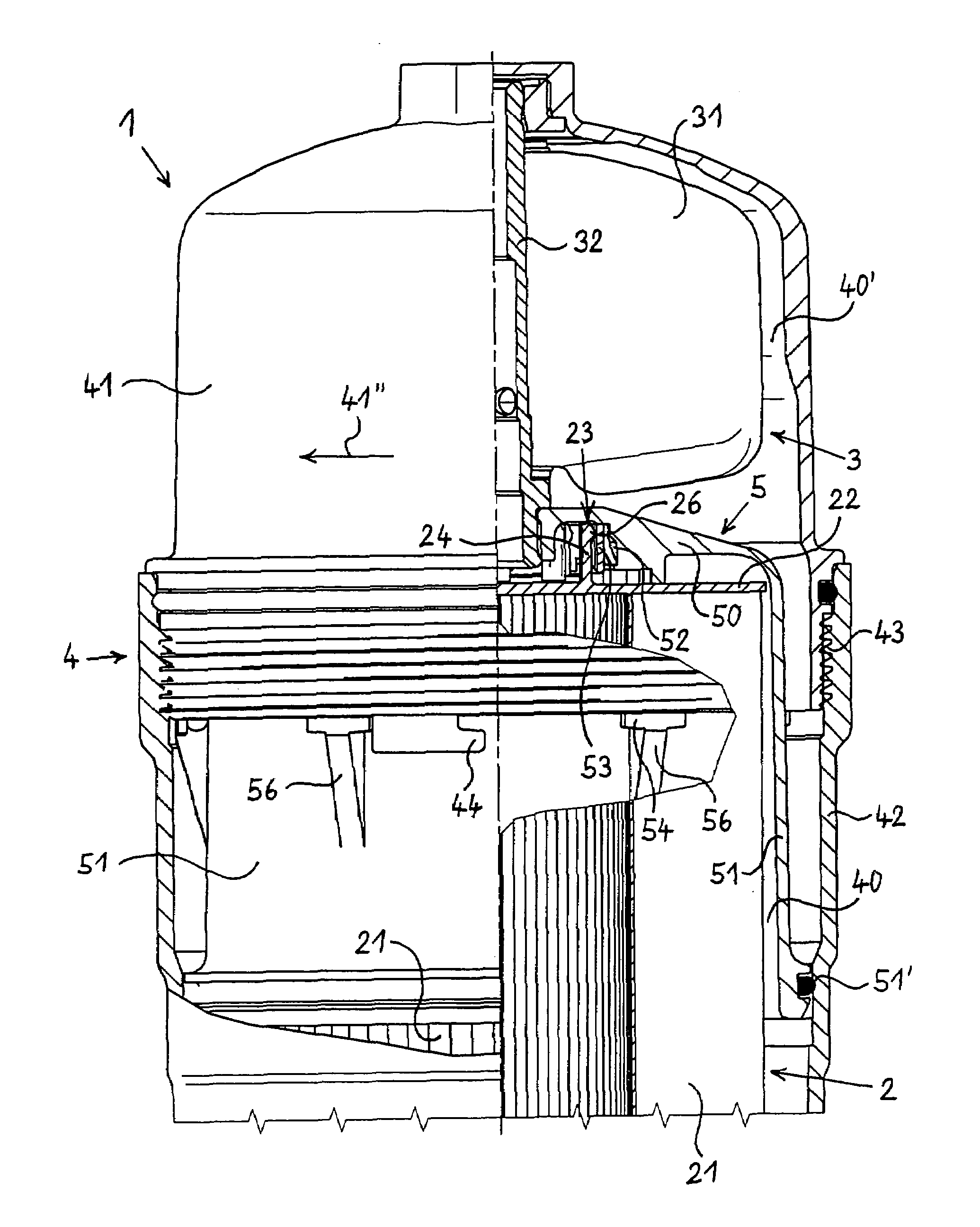
[0058]As shown in FIG. 3 of the drawing, the represented second embodiment of the device 1 for separating impurities from the lubricating oil of an internal combustion engine also comprises a housing 4, which is formed by a lower stationary housing part 42 and an upper screw cap 41. The screw cap 41 can be screwed into the stationary housing part 42 by means of the threaded connection 43 that is sealed by a gasket, wherein the screw cap 41 is shown in FIG. 1 in its securely tightened state.

[0059]A filter element 2 in the form of a filter medium body 21 with an upper end disk 22 and a lower end disk that is not visible here is arranged in the lower part of the housing 4. A centrifuge 3 comprising a rotor 31 that is pivoted on a rotational axis 32 is provided in the upper part of the housing 4 flush with and above the filter element 2.

[0060]The interior region of the housing 4 is subdivided in a lower region 40 and an upper region 40′ by a bell-shaped intermediate cap 5. The intermedi...

third embodiment

[0075]FIGS. 9 through 12 show a device 1, which also comprises a centrifuge 3 and a filter element 2 inside a common housing 4.

[0076]The longitudinal section according to FIG. 9 shows this arrangement in the housing 4, with the centrifuge 3 at the top and the filter element 2 at the bottom. Here as well, the housing 4 is provided with a stationary lower housing part 42 and a screw cap 41 that is connected thereto via a thread 43 and can be rotated in its loosening rotational direction. The intermediate cap 5 subdivides the interior region of the housing 4 in a lower housing region 40 that accepts the filter element 2 and an upper housing part40′ that accepts the centrifuge 3. Here as well, the intermediate cap 5 has the approximate shape of a bell and possesses a curved upper part 50 as well as a circumferential region 51 arranged adjacent thereto in downward direction. At the bottom of this circumferential region 51, a gasket 51′ is inserted in a groove that points in a radially ou...


PUM

PropertyMeasurementUnit
Angleaaaaaaaaaa
Angleaaaaaaaaaa
Angleaaaaaaaaaa

Abstract

Devices for separating impurities from the lubricating oil of an internal combustion engine, the devices at least having a filter element and a housing provided with a screw cap. The screw cap and the filter element include a detachable connection arrangement which can be brought into contact and are used to transmit axial tractive forces. A first device is characterized in that the connection arrangement can be brought into contact by rotating the screw cap in the loosening rotational direction thereof and can be disengaged by rotating the screw cap in the tightening rotational direction thereof. A second device also includes a centrifuge located in the same housing, a first connection apparatus, corresponding to the above-mentioned connection apparatus being provided between an intermediate cap and the filter element, and a second connection apparatus being provided between the screw cap and the intermediate cap.

Description

BACKGROUND OF THE INVENTION[0001]The present invention relates to a device for separating impurities from the lubricating oil of an internal combustion engine, said device comprising a filter element, wherein said filter element is arranged in a two-piece housing that is closed during operation of the device and comprises a stationary lower housing part and a removable upper screw cap and wherein said screw cap and said filter element comprise detachable connection means which can be brought into contact and are used to transmit axial tractive forces, wherein the filter element is removed from the housing by means of these connection means when the screw cap is rotated in its loosening rotational direction.[0002]Furthermore, the present invention relates to a device for separating impurities from the lubricating oil of an internal combustion engine, said device comprising a filter element at its bottom and, on top of said filter element, a centrifuge with a rotor drivable by means o...

Claims


Application Information

Patent Timeline
IPC IPC(8): B01D35/00B01D29/96B01D35/30B01D36/04B04B5/00C10M175/00F01M11/03
CPCB01D29/96B01D35/30B01D36/045B04B5/005C10M175/0058B01D2201/4015B01D2201/4084F01M2001/1035Y10S55/17
Inventor BAUMANN, DIETER
Owner HENGST WALTER
Why Eureka
Try Eureka