
Ionizer

a technology of ionizer and electrode needle, which is applied in the field of ionizer, can solve the problems of reducing the amount of ion generated, the operation of ionizer and related facilities must be stopped, and the difficulty of corona discharge, etc., and achieves the reduction of the frequency of maintenance, cleaning and exchanging of the electrode needle, and the effect of reducing the dirt on the electrode needle due to the adhesion of dus

Inactive Publication Date: 2009-03-03
SMC CORP
View PDF21 Cites 38 Cited by
  • Summary
  • Abstract
  • Description
  • Claims
  • Application Information

AI Technical Summary

Benefits of technology

"The present invention provides an ionizer with a function for suppressing adhesion of dust to the electrode needle and easily removing the dust. The ionizer includes a housing with an electrode-attaching portion, positive and negative electrode needles, and an air-blowing outlet. The air-blowing outlet is open in the electrode-attaching portion and a spatial portion inside the protection cover. The protection cover has air-blowing holes and air-flowing outlets to allow air to flow out of the protection cover. The ionizer is designed to prevent dust from accumulating on the electrodes and to easily clean them. The technical effects of the invention are to improve the performance and reliability of the ionizer by preventing electrode fouling and to provide a more convenient and efficient solution for removing dust."

Problems solved by technology

In this kind of ionizer, the positive and negative electrode needles tend to foul by adhesion of dust in the air, and when the fouling operation proceeds, a generating amount of the ion is being reduced because of the generation of the corona discharge gradually becomes difficult.
Therefore, this requires frequent maintenance such as a cleaning operation, an exchanging operation, and so forth for the foul electrode needle, and during the time when the maintenance is performed, operations of the ionizer and related facilities have to be stopped.
Consequently, there has been a problem such as that an operating efficiency tends to be lowered while taking trouble and wasting time.

Method used


Image

  • Ionizer
  • Ionizer
  • Ionizer

Examples


Embodiment Construction

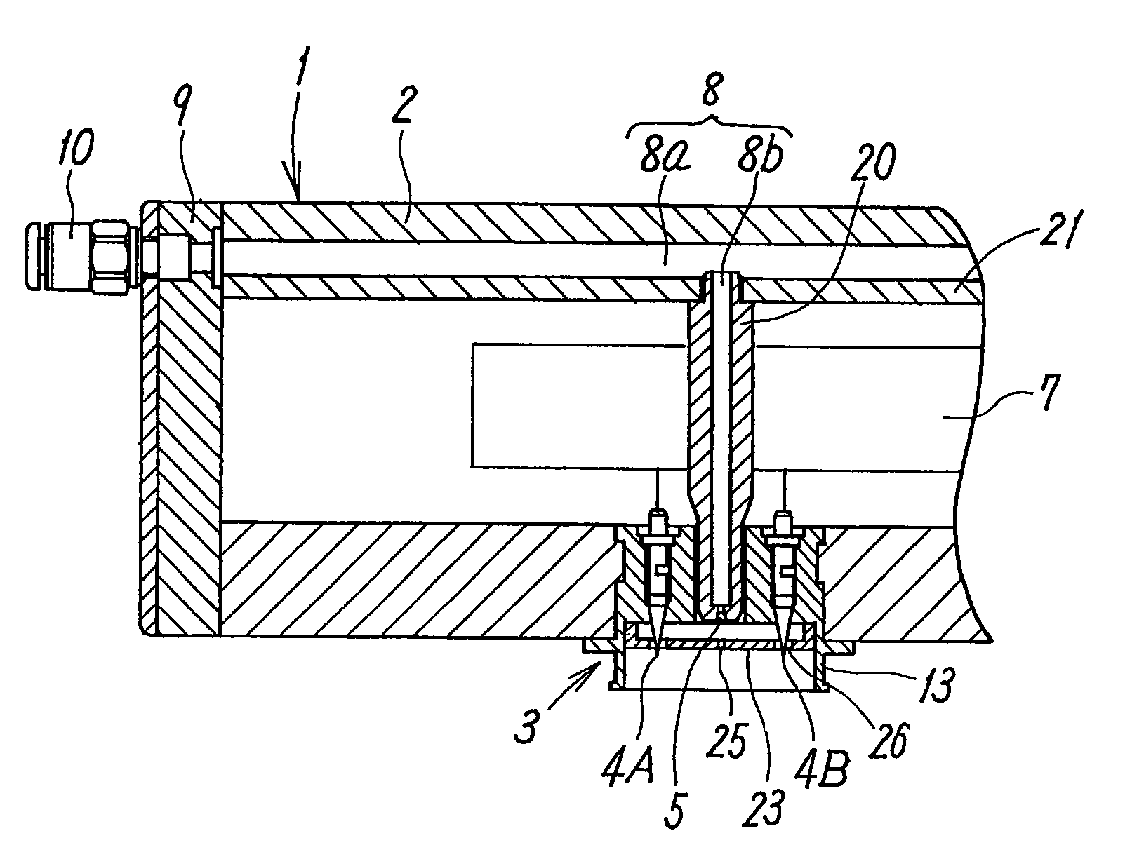
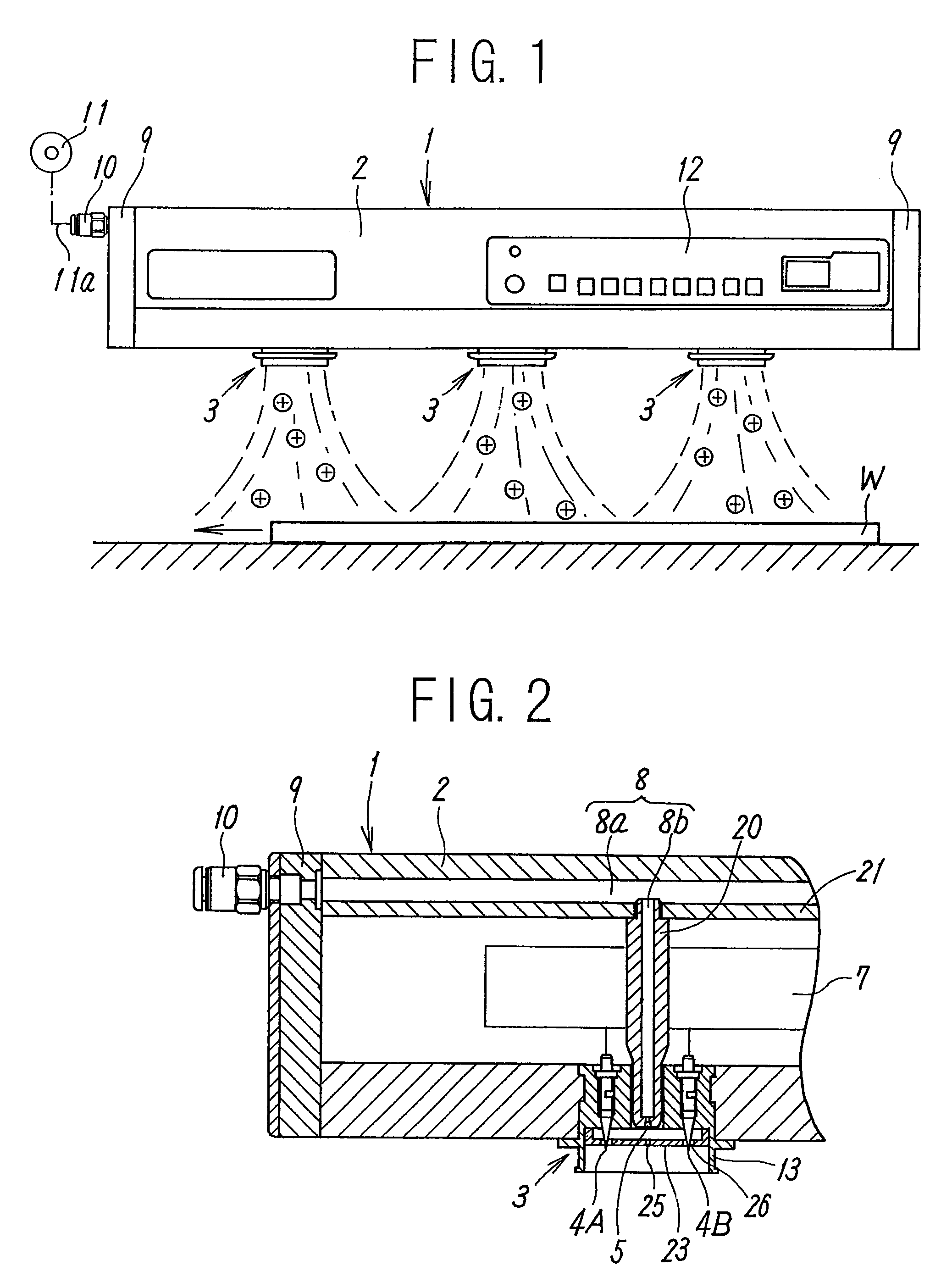
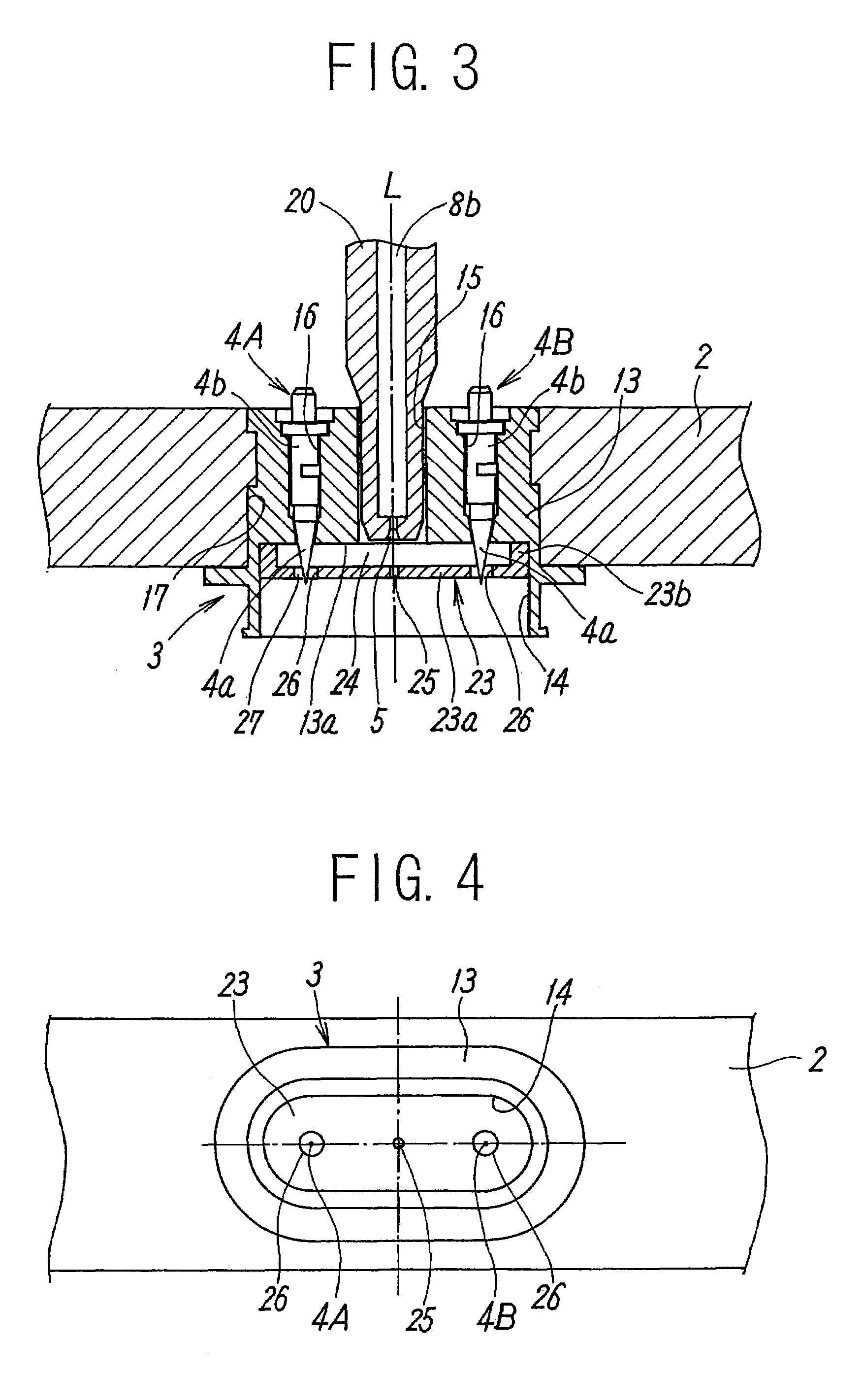
[0030]FIG. 1 through FIG. 4 illustrate an embodiment of an ionizer according to the present invention. This ionizer 1 is used for discharging the workpiece which is electrostatically charged in a treating process for various types of workpieces such as a semiconductor wafer, liquid crystal glass, and so forth, and as illustrated in FIG. 1, when positive and negative ions are alternately applied from this ionizer 1 to a workpiece W, and in a case that the workpiece W is charged to be positive, a negative ion is absorbed by the workpiece W, and in a case that the workpiece W is charged to be negative, a positive ion is absorbed by the workpiece W. Thus, the workpiece W is discharged. Incidentally, although a moment when the positive ion is applied is illustrated in FIG. 1, the negative ion is successively applied thereafter in a similar manner as that mentioned above.

[0031]The ionizer 1 is a bar-type ionizer having a thin long rod shape, and provided with a laterally thin long hollow ...


PUM


Abstract

Positive and negative electrode needles, an air-blowing outlet, and a protection cover for covering these electrode needles and the air-blowing outlet are attached to an electrode cartridge which is attached to a housing, and an air-blowing hole positioned in front of the air-blowing outlet in a concentric manner therewith, for blowing out air from the air-blowing outlet toward the outside, and two air-flowing-out holes positioned in a concentric manner with the respective positive and negative electrode needles, and respectively surrounding outer peripheries of respective tip end portions of respective electrode needles via respective gaps for flowing out the air are formed in the protection cover.

Description

TECHNICAL FIELD[0001]The present invention relates to an ionizer used for discharging various kinds of electrostatically charged workpieces, and more in detail, to an ionizer provided with a function for preventing an electrode needle from fouling due to adhesion of dust.BACKGROUND ART[0002]In a treating process for various types of workpieces such as a semiconductor wafer, liquid crystal glass, and so forth, an ionizer is used for discharging the workpiece, which is electrostatically charged. The ionizer is constructed, as described in, for example, Japanese Unexamined Patent Application Publication No. 2005-108829, such that a positive electrode needle and a negative electrode needle are disposed in parallel with each other in an electrode-attaching opening at a lower surface of a housing, and that positive and negative ions are alternately generated by generating a corona discharge at both the electrode needles by means of alternately applying a positive pulsing high voltage and ...

Claims


Application Information

Patent Timeline
Patent Type & Authority Patents(United States)
IPC IPC(8): B03C3/80
CPCB03C3/383B03C2201/06
Inventor SATO, TOSHIOSUZUKI, SATOSHIYASUOKA, TAKASHI
Owner SMC CORP
Learn More