Motor control method and motor control apparatus

a motor control and control method technology, applied in the direction of motor/generator/converter stopper, electronic commutator, dynamo-electric converter control, etc., can solve the problems of abnormal rotation, abnormal rotation of the motor cannot be detected, speed deviation becomes large during acceleration or deceleration of the motor, etc., to achieve the effect of increasing protection performan

Active Publication Date: 2009-03-03
FANUC LTD
View PDF6 Cites 26 Cited by
  • Summary
  • Abstract
  • Description
  • Claims
  • Application Information

AI Technical Summary

Benefits of technology

[0013]In order to solve the above problem, it is an object of the present invention to provide a method of controlling a motor and a motor control apparatus that have a function of detecting a runaway of a motor controlled by software servo and that can instantly detect an abnormal rotation of a motor during acceleration or deceleration of the motor to be able to increase the protection performance of the motor.
[0018]When it is desired to change an overspeed level to prevent a speed from exceeding a specific level for a main spindle having many kinds of tools, this can be done by changing the setting of the overspeed level for each tool. However, it is troublesome to change the setting of the overspeed level each time when a tool is replaced. According to the present invention, an operator sets a speed command by recognizing a rotation speed for each tool. When a determination speed is added to this speed command to set an overspeed level, the overspeed level necessary for each tool can be automatically set, thereby avoiding the work of resetting the overspeed level. Further, a determination speed can be externally set. The overspeed level can be changed by adding a speed command to this determination speed. Therefore, when the determination speed is externally changed according to a mechanical condition, the overspeed level can be changed more accurately. When a speed command is reset to zero or when a control mode is changed from a speed control mode to a position control mode, it is regarded that a mechanical condition has changed. By resetting the overspeed level, the overspeed level can be set for each tool.
[0020]The present invention has been made to prevent an abnormal rotation that occurs when a number of pulses of a speed sensor or a number of poles of a motor is set wrong, by miscounting a feedback due to noise or the like. When there are these influences, a magnetic-pole position is calculated at a position different from the actual position. Accordingly, the magnetic-pole position recognized by control software is deviated from the actual magnetic-pole position of the motor. As a result, the motor cannot be operated normally, and an abnormal rotation of the motor occurs. According to the present invention, an abnormal rotation can be prevented in advance, by detecting a deviation of a magnetic-pole position and giving an alarm.
[0021]The present invention is provided for the case where a synchronous motor is driven in a high-speed rotation that requires a weak magnetic field system. In order to safely stop the motor when an abnormal rotation of the motor is detected, a short-circuiting device disposed between a power converter and a synchronous motor receives a short-circuiting device starting signal, opens a terminal at the power converter side, and short-circuits a terminal at the synchronous motor side. When the motor is in an abnormal-rotation (runaway) state, the motor cannot be stopped. Therefore, a power supply to the motor can be stopped, thereby free running the motor. However, when the motor is free run in a high-speed rotation state which requires a weak magnetic field, there is a risk that the synchronous motor operates as a power generator, and a voltage at a power converter increases to damage the power converter, because the synchronous motor is in a state of generating a high back surge. The present invention short-circuits a stator winding of the synchronous motor to prevent damaging of the power converter, and to safely stop the synchronous motor.
[0022]According to the present invention, when it is determined that there is a possibility of the motor being in a runaway state, a speed deviation is integrated, and when this value exceeds a threshold value, the motor can be determined in a runaway state. Therefore, as compared with the motor control apparatus according to the conventional technique, the apparatus according to the present invention can quickly detect an abnormal state.
[0024]Further, according to the present invention, a motor control method and a motor control apparatus have a function of detecting a runaway of a motor controlled by software servo. Therefore, an abnormal rotation of the motor can be detected instantly, thereby increasing protection performance, even during acceleration or deceleration of the motor.

Problems solved by technology

However, according to these methods of detecting an abnormal rotation of a motor based on conventional techniques, when an input speed command changes stepwise, a speed deviation becomes large during acceleration or deceleration of the motor.
Consequently, there is a problem that even when an abnormal rotation of a motor occurs during acceleration or deceleration, this abnormal rotation cannot be detected.
Therefore, when a high speed command is input stepwise and when the motor causes a runaway in an opposite direction, the abnormal rotation of the motor cannot be detected until when a rotation speed of the motor exceeds a predetermined high value that determines an overspeed protection range.
Further, an overspeed detector that protects the motor from an overspeed does not operate.
Therefore, there is also a problem that a detection of the abnormal rotation of the motor becomes slow.
Therefore, there is a problem that this method and this apparatus cannot be used for a main spindle servomotor that uses, in many cases, a speed command motor having no position feedback.

Method used


Image

  • Motor control method and motor control apparatus
  • Motor control method and motor control apparatus
  • Motor control method and motor control apparatus

Examples


Embodiment Construction

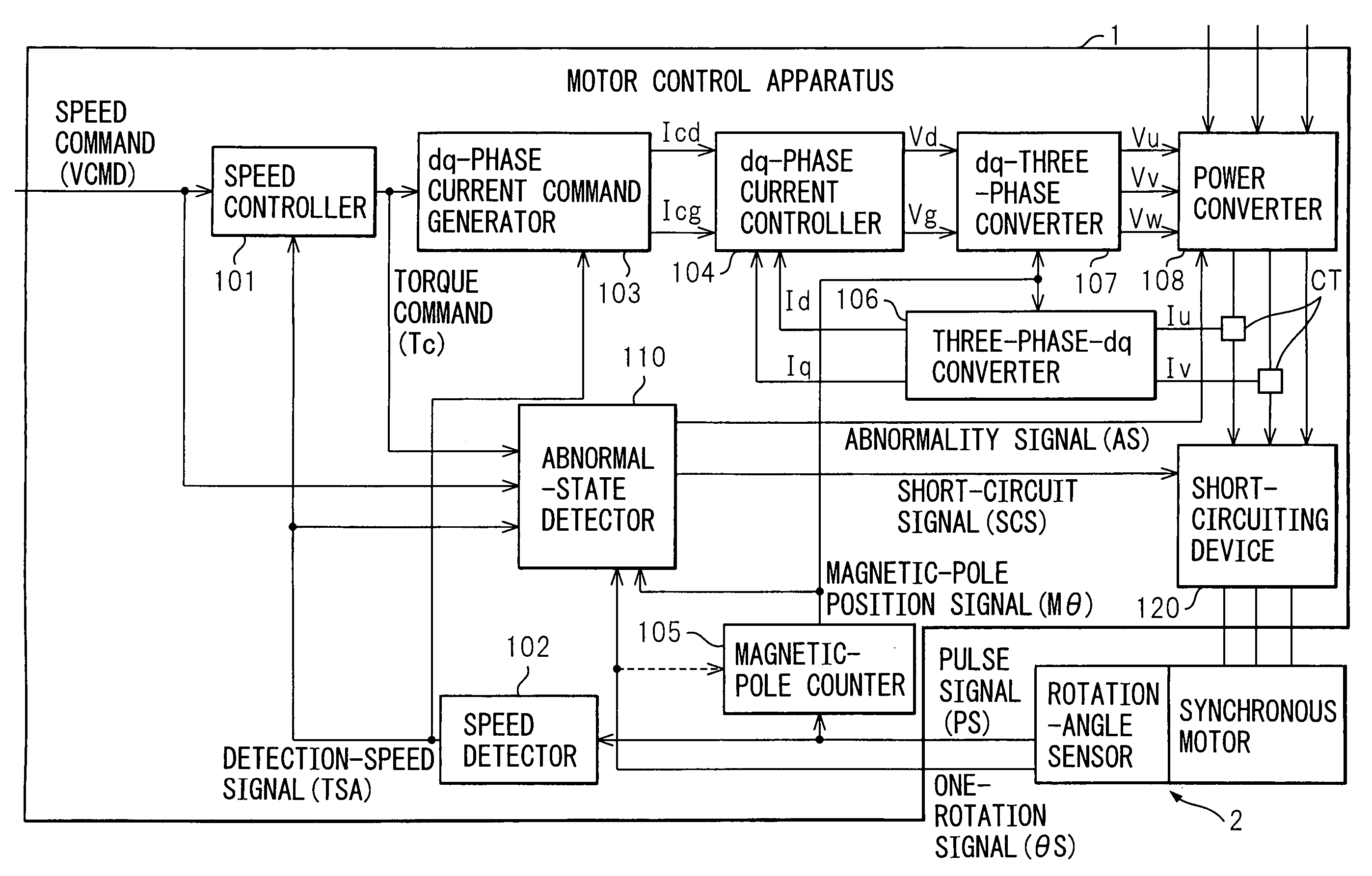
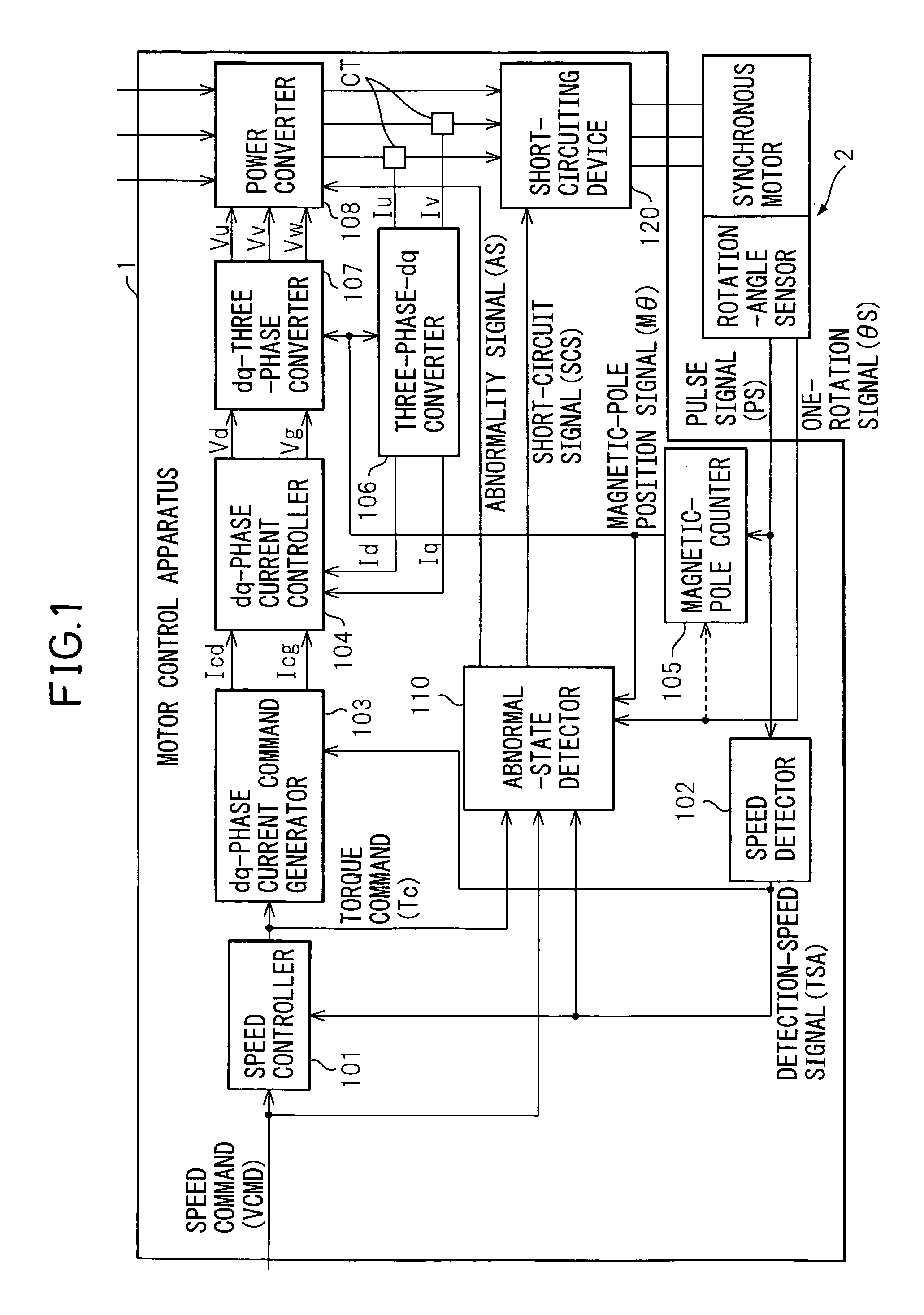
[0036]FIG. 1 is a schematic block configuration diagram of a motor control apparatus according to the present invention. A motor control apparatus 1 shown in FIG. 1 is an apparatus that controls a speed and a current of a synchronous motor (hereinafter referred to as a motor) 2. A speed controller 101 receives a speed command VCMD from a numerical controller (hereinafter referred to as an NC) mounted outside such as a programmable controller (hereinafter referred to as a PMC) not shown, and a detection speed signal TSA that is obtained by converting a pulse signal PS output from a rotation angle sensor built in the motor 2 into a rotation speed of the motor by a speed detector 102. The speed controller 101 calculates a speed deviation Ver (=VCMD−TSA), proportionally integrates (PI) this Ver to obtain a torque command Tc, and outputs this Tc. The rotation angle sensor is an incremental encoder, for example, that detects a rotation angle of a rotation axis of the motor 2.

[0037]A dq-ph...


PUM


Abstract

A motor control apparatus 1 that controls a rotation speed of a motor driven according to a speed command includes an abnormal-rotation detector 21 which determines that the motor is in an abnormal-rotation state, such as a runaway, when a speed deviation Ver obtained by subtracting a detection speed TSA of a motor rotation from a speed command VCMD is equal to or larger than a threshold value, when a sign of a product of acceleration ΔTSA obtained by subtracting a last detection speed from a detection speed this time that is detected in a predetermined cycle and a torque command Tc obtained by proportionally integrating the speed deviation is negative, and when an integration value VerSUM of the speed deviation Ver exceeds a predetermined value ALMlevel. With this arrangement, an abnormal rotation of the motor can be instantly detected even during acceleration or deceleration of the motor, thereby increasing the performance of protecting the motor.

Description

BACKGROUND OF THE INVENTION[0001]1. Field of the Invention[0002]The present invention relates to a motor control method and a motor control apparatus. Particularly, the invention relates to a motor control method and a motor control apparatus having a function of detecting a state of an abnormal rotation, including runaway, of a motor that is controlled by a software servo.[0003]2. Description of the Related Art[0004]According to a conventional method of detecting an abnormal rotation of a motor, when a speed deviation of a speed feedback to an instructed speed exceeds a predetermined threshold value, this abnormal rotation of the motor is detected as a speed deviation excess.[0005]The following patent document 1 has the title “Overspeed Protection Method for Motor Driven by Inverter Equipment”, and discloses a method of changing an overspeed protection range according to a speed command signal.[0006]The following patent document 2 has the title “Method of Detecting a Runaway of a M...

Claims


Application Information

Patent Timeline
Patent Type & Authority Patents(United States)
IPC IPC(8): H02P1/24H02P6/06H02P6/08H02P6/12H02P6/17H02P29/00H02P29/02
CPCH02P29/028H02P29/032H02P29/10
Inventor IWASHITA, YASUSUKETOYOZAWA, YUKIOTAKAHASHI, KENJI
Owner FANUC LTD
Why Eureka
Try Eureka