Real-time precision ray tracing

a real-time, precision technology, applied in the field of image rendering, can solve the problems of slow setup of acceleration data structures, limited ability to process dynamic scenes, and known limitations of current ray tracing techniques, and achieve the effect of efficient determination of splitting planes

Inactive Publication Date: 2009-03-03
MENTAL IMAGES
View PDF18 Cites 26 Cited by
  • Summary
  • Abstract
  • Description
  • Claims
  • Application Information

AI Technical Summary

Benefits of technology

[0014]Another aspect of the present invention addresses the issue of self-intersection in ray tracing. A technique is described below wherein, after computing the intersection point of a ray and a surface, the computed point is used, along with the ray direction, to re-compute the ray / surface intersection point, thereby providing an iteration that increases precision.
[0015]Another aspect of the present invention enables high performance 3D-tree construction via optimizations in splitting plane selection, minimum storage construction, and tree pruning via approximate left-balancing.
[0017]Another aspect of the invention involves efficiently determining a splitting plane M via a 3D-tree construction technique described herein, and then partitioning the objects such that the overlap of the resulting L- and R-planes of the new axis-aligned bounding boxes is minimally overlapping the suggested splitting plane M.

Problems solved by technology

However, current ray tracing techniques suffer from a number of known limitations and weaknesses, including numerical problems, limited capabilities to process dynamic scenes, slow setup of acceleration data structures, and large memory footprints.
Thus, current ray tracing techniques lack the capability to deal efficiently with fully animated scenes, such as wind blowing through a forest or a person's hair.
Current attempts to improve the performance of ray tracing systems have fallen short for a number of reasons.
Because the main focus of these systems is on rendering static scenes, they typically fail to address the significant amount of setup time required to construct the required data structures in connection with fully animated scenes.
However, it has been found that the architecture's performance breaks down if too many incoherent secondary rays are traced.
The construction of acceleration structures has not yet been implemented in hardware.

Method used


Image

  • Real-time precision ray tracing
  • Real-time precision ray tracing
  • Real-time precision ray tracing

Examples


Embodiment Construction

[0025]The present invention provides improved techniques for ray tracing, and for the efficient construction of acceleration data structures required for fast ray tracing. The following discussion describes methods, structures and systems in accordance with these techniques.

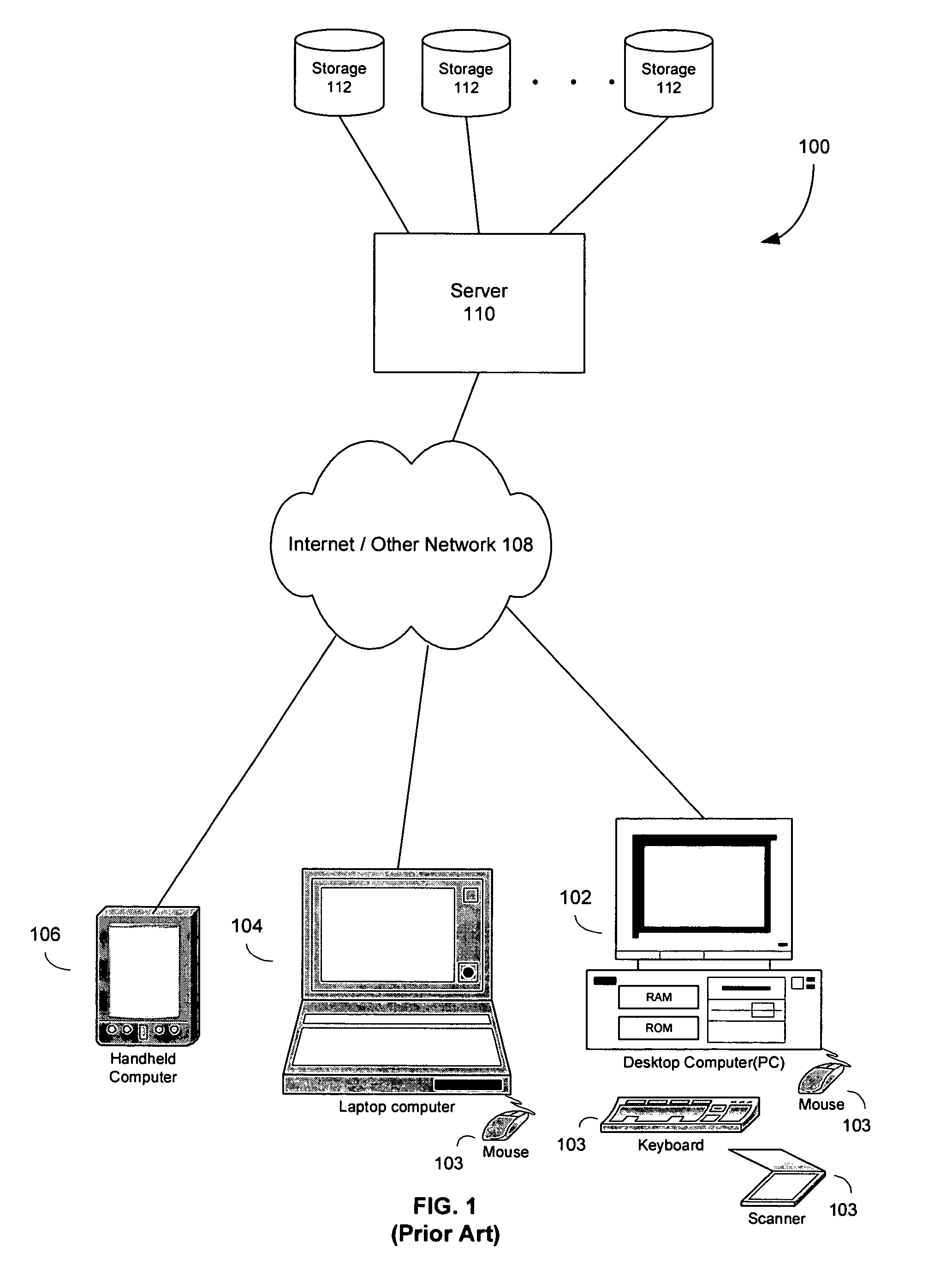
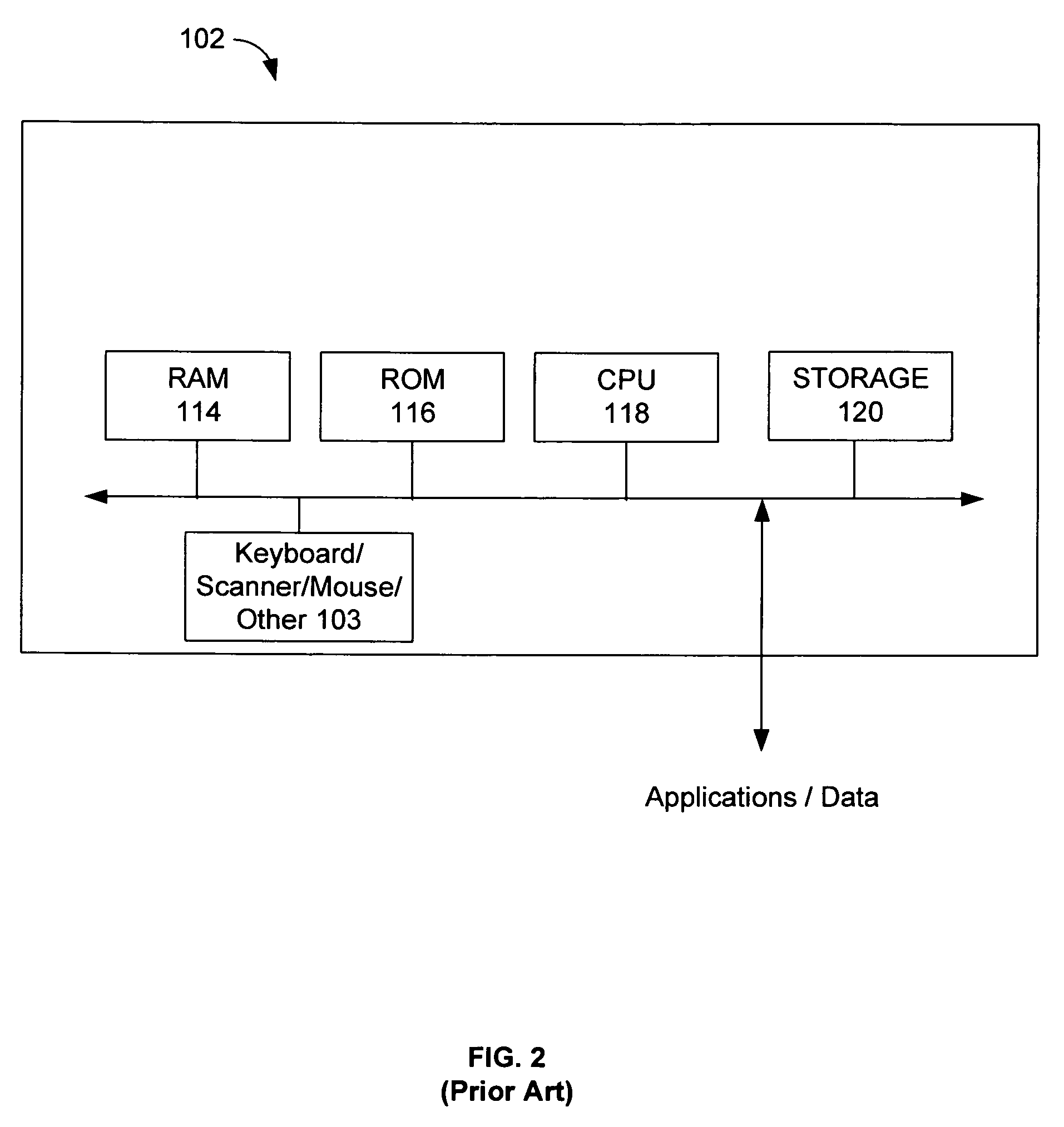
[0026]It will be understood by those skilled in the art that the described methods and systems can be implemented in software, hardware, or a combination of software and hardware, using conventional computer apparatus such as a personal computer (PC) or equivalent device operating in accordance with, or emulating, a conventional operating system such as Microsoft Windows, Linux, or Unix, either in a standalone configuration or across a network. The various processing means and computational means described below and recited in the claims may therefore be implemented in the software and / or hardware elements of a properly configured digital processing device or network of devices. Processing may be performed sequen...


PUM


Abstract

Systems and techniques are described for ray tracing and for the efficient construction of acceleration data structures required for fast ray tracing. A computer graphics system generates, for each pixel in an image, a pixel value that is representative of a point in a scene as recorded on an image plane of a simulated camera. The computer graphics system is configured to generate the pixel value for an image using a selected ray-tracing methodology. The selected ray-tracing methodology includes the use of a ray tree that includes at least one ray shot from the pixel into a scene along a selected direction. The ray-tracing methodology further includes calculating the intersections of rays and surfaces in the scene. An axis-aligned bounding box is defined that contains, for a given ray, the point of intersection of the ray and surface nearest the origin of the ray. The bounding box is iteratively refined until a predetermined termination criterion has been met.

Description

CROSS-REFERENCE TO RELATED APPLICATIONS[0001]The present application is a Continuation-In-Part of U.S. patent application Ser. No. 10 / 299,574 filed Nov. 19, 2002 (issued as U.S. Pat No. 7,184,042), which is a Continuation-In-Part of U.S. Ser. No. 09 / 884,861 filed Jun. 19, 2001 (issued as U.S. Pat. No. 7,227,547), which claims priority benefit from provisional applications No. 60 / 265,934 filed Feb. 1, 2001 (expired) and 60 / 212,286 filed Jun. 19, 2000 (expired) each of which is incorporated by reference.[0002]The present application claims the benefit of United States Provisional Patent Application Ser. No. 60 / 693,231, filed on Jun. 23, 2005 (expired), which is hereby incorporated by reference in its entirety.REFERENCE TO COMPUTER PROGRAM APPENDIX[0003]Submitted herewith is a source code listing, which is incorporated herein in its entirety. The source code listing is referred to herein as the “Appendix,” and is organized into sections identified by a three-digit reference number in t...

Claims


Application Information

Patent Timeline
Patent Type & Authority Patents(United States)
IPC IPC(8): G06T15/50G06T15/60
CPCG06T15/06G06T15/40G06T15/506G06T15/55
Inventor KELLER, ALEXANDERWAECHTER, CARSTEN
Owner MENTAL IMAGES
Why Eureka
Try Eureka