Fastener tightening analysis

a technology of fasteners and tighteners, applied in the field of fastener tightening analysis, can solve the problem that more complex connections may not be dealt with in a fully satisfactory manner

Inactive Publication Date: 2009-03-03
DASSAULT SYSTEMES
View PDF2 Cites 37 Cited by
  • Summary
  • Abstract
  • Description
  • Claims
  • Application Information

AI Technical Summary

Problems solved by technology

However, more complex connections may not b

Method used


Image

  • Fastener tightening analysis
  • Fastener tightening analysis
  • Fastener tightening analysis

Examples


Embodiment Construction

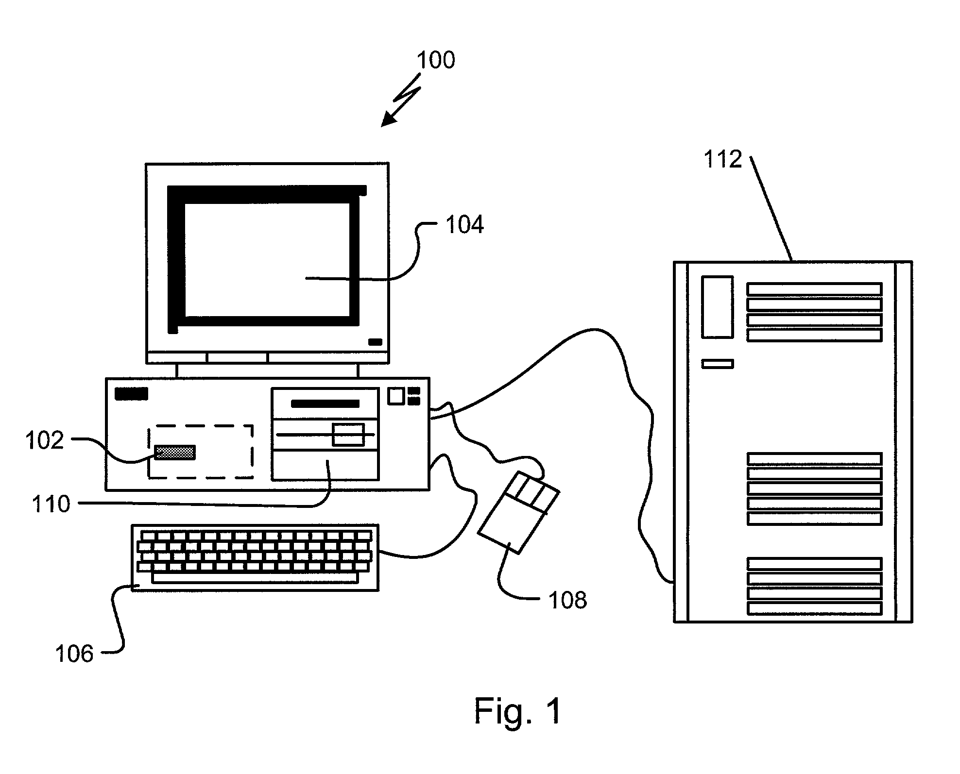
[0014]FIG. 1 shows a computerized modeling system 100 that includes a CPU 102, a CRT 104, a keyboard input device 106, a mouse input device 108, and a storage device 110. The CPU 102, CRT 104, keyboard 106, mouse 108, and storage device 110 can include commonly available computer hardware devices. For example, the CPU 102 can include a Pentium-based processor. The mouse 108 may have conventional left and right buttons that the user may press to issue a command to a software program being executed by the CPU 102. Other computer hardware platforms are suitable as will become apparent from the discussion that follows. Such computer hardware platforms are preferably capable of operating the Microsoft Windows NT, Windows 95, Windows 98, Windows 2000, or UNIX operating systems.

[0015]Computer-aided design software is stored on the storage device 110 and is loaded into and executed by the CPU 102. The software allows the design engineer to create and modify a three dimensional (3D) model an...


PUM


Abstract

Analyzing the mechanical state of an assembly modeled by a computer aided design system includes generating a model of a fastener and a part of the assembly. The fastener model includes an engaging region and the part model includes a receiving region to fastenably receive the engaging region. The fastener and the part are each represented by finite element representations that include elastically interconnected nodes. A tightening mesh interconnecting nodes of the engaging region and nodes of the receiving region is generated and a force applied between the nodes of the engaging and receiving region is determined based on a pre-tension force occurring upon engaging the engaging region with the receiving region.

Description

BACKGROUND OF THE INVENTION[0001]In designing mechanical part assemblies using computer aided design, manufacturing, and engineering (CAD / CAM / CAE) systems, it is useful to simulate and analyze the structural behavior of an assembly under operating conditions and the stresses experienced by the assembly under those operating conditions. Stress simulation and analysis operations are usually based on a geometrical discretization of the assembly using a finite element mesh representation of each part body in the assembly. Each mesh is usually comprised of nodes and elements interconnecting the nodes. These nodes and elements may take the form of solid elements such as tetrahedrons, hexahedrons, cubes, etc, surface elements such as triangles, quadrangles, and so-called 1-D elements such as bars and interconnecting links. Techniques for constructing such nodes and elements are described in, e.g., The Finite Element Method by O. C. Zienkiewicz and R. L. Taylor, McGraw Hill, 1989 [ref. 1], ...

Claims


Application Information

Patent Timeline
IPC IPC(8): G06G7/48
CPCG06F17/5018G06F30/23
Inventor QUINCY, JEAN-BAPTISTESAVINIEN, EMMANUELDEHILLERIN, CHARLES-ANDRENAVEAU, CHRISTIAN
Owner DASSAULT SYSTEMES
Why Eureka
Try Eureka