Method and apparatus for shaping a metallic container end closure

a technology of end closure and metal container, which is applied in the field of manufacturing process of forming metallic containers and container end closures, can solve the problems of inconsistencies in the geometry of end closures, inconsistencies within a given contour or geometry, etc., and achieve the effect of improving strength characteristics and material properties

Active Publication Date: 2009-03-10
BALL CORP
View PDF215 Cites 46 Cited by
  • Summary
  • Abstract
  • Description
  • Claims
  • Application Information

AI Technical Summary

Benefits of technology

[0006]The present invention relates to an apparatus and method for forming a preferred geometric shape in containers and end closures utilizing thin walled materials (0.0084 or less gauge) which have improved strength characteristics and material properties. Thus, in one aspect of the present invention a “free forming” process is used in the manufacturing of a metallic container end closure, wherein at least a portion of the material is placed in compression during forming, and is thus less likely to become “coined” or thinned, and ultimately weakened. It is a further aspect of the present invention to provide a method and apparatus for forming a predetermined shape from a metallic material wherein a portion of the metallic material is unsupported by a tool during formation. Thus, a portion of the metallic material is allowed to “free form” into a desired shape without being substantially supported on both the entire upper or lower surface of the material.
[0007]It is a further aspect of the present invention to provide a forming press to form a preferred geometry in a metallic end closure with existing high speed forming processes currently known in the industry and having improved reliability. Thus, in one aspect of the present invention an inner pressure sleeve is utilized in combination with critical forming parameters to assure that the end closure achieves a predetermined geometry, and is extracted efficiently from the forming process at speeds of 1800-11,000 end closures / minute.
[0013]providing a reciprocating motion between at least said fifth tool and said first and second tools while a portion of a countersink in the container end closure remains unsupported, wherein a preferred geometry is created in the countersink producing a material thickening, thus avoiding a reduction of material thickness of the countersink.
[0017]providing a clamping force on at least a portion of the central panel between a third tool and a fourth tool to substantially prevent movement of the central panel;
[0018]supporting at least a portion of the chuckwall on both an interior surface and an exterior surface to substantially prevent movement of at least a portion of the chuckwall;

Problems solved by technology

Unfortunately, this process may lead to inconsistencies within a given contour or geometry.
Formation inconsistencies also apply to strength performance.
Unfortunately, with lighter gage stock materials this process has been found to allow unwanted deformation in the chuck wall and seaming crown, and thus inconsistencies in the end closure geometry.

Method used


Image

  • Method and apparatus for shaping a metallic container end closure
  • Method and apparatus for shaping a metallic container end closure
  • Method and apparatus for shaping a metallic container end closure

Examples


Embodiment Construction

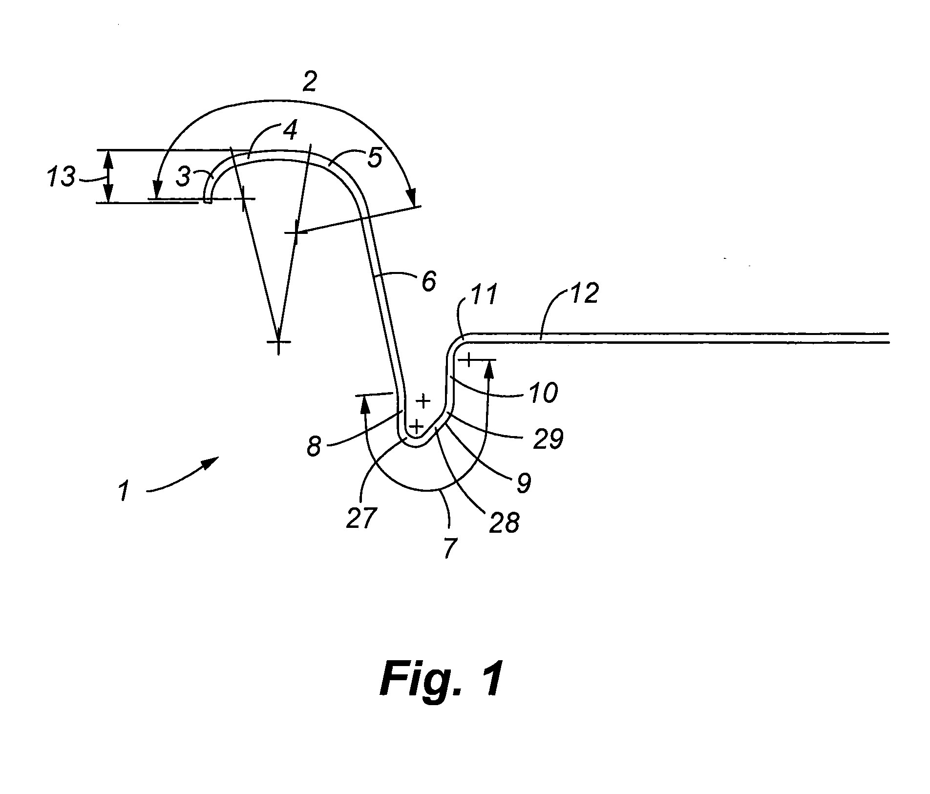
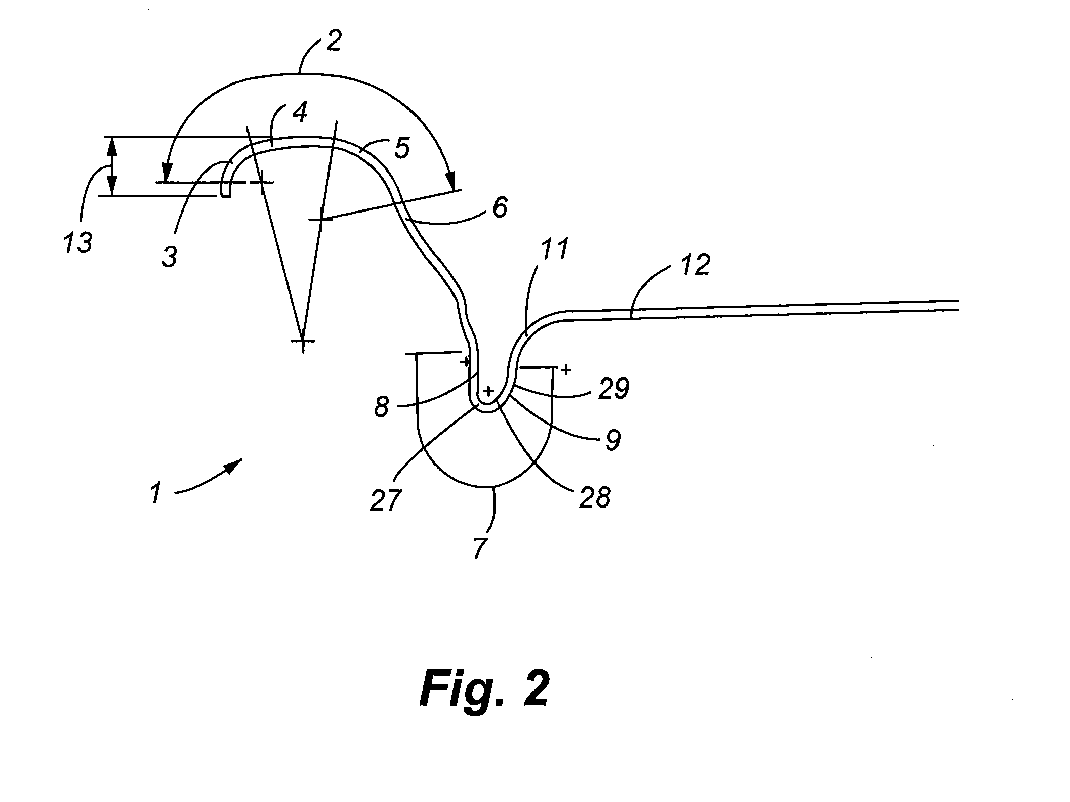
[0046]Referring now to FIGS. 1-3, cross-sectional front elevation views are provided of alternative embodiments of uncurled beverage can end closures capable of being formed with the process defined herein. Other end closure geometries not shown herein may also be formed using the invention described herein as appreciated by one skilled in the art. More specifically, a metallic beverage can end closure 1 is generally comprised of a circular seaming panel 2, a chuck wall 6, a countersink 7, a central panel 12, and an inner panel radius 11 which interconnects the central panel 12 to the countersink 7. Further, the uncurled seam height 13 may extend beyond the seaming panel 2. The circular seaming panel 2 is additionally comprised of an outer seaming panel radius 3, seaming panel radius 4, and inner seaming panel radius 5. The seaming panel 2 is designed for interconnection to a neck of a container by double seaming or other methods well known in the art. The countersink 7 is generally...


PUM

PropertyMeasurementUnit
shapeaaaaaaaaaa
clamping forceaaaaaaaaaa
compressive forceaaaaaaaaaa

Abstract

The present invention describes an apparatus and forming process to manufacture container end closures with improved internal buckle strength. The present invention provides greater material and dimensional control during the forming process by utilizing a pressure sleeve to provide support to at least a portion of an end closure chuck wall and seaming panel radius while placing an end closure countersink in compression during the forming process.

Description

[0001]This application claims the benefit of U.S. Provisional Patent Application Ser. No. 60 / 592,784, filed Jul. 29, 2004, which is incorporated by reference in its entirety herein.FIELD OF INVENTION[0002]The present invention relates to a manufacturing process for forming metallic containers and container end closures, and more specifically a method and apparatus for forming high strength geometries while maintaining necessary chuck wall and seaming panel characteristics.BACKGROUND OF INVENTION[0003]Metallic beverage can end closures have historically been designed and manufactured to provide a stiffening bead referred to as countersink. This feature may include vertical walls attached by a full radius bottom forming a channel, and in some embodiments may incorporate arcuate shapes or other geometric profiles. Absolute vertical walls may not exist, but generally the more vertical they become the greater the resistance to deformations resulting from internal pressure.[0004]Beverage ...

Claims


Application Information

Patent Timeline
Patent Type & Authority Patents(United States)
IPC IPC(8): B21D22/00
CPCB21D22/24B21D51/38
Inventor BATHURST, JESS N.TRAPHAGEN, JAMES D.
Owner BALL CORP
Why Eureka
Try Eureka