
Heat exchanger and method of manufacturing the same

a technology of heat exchanger and expander, which is applied in the direction of indirect heat exchanger, tubular elements, lighting and heating apparatus, etc., can solve the problem of not being able to insert a sufficiently rigid expander, and achieve the effect of facilitating the downward flow of water droplets, low pressure loss, and high heat exchange efficiency

Inactive Publication Date: 2009-03-10
DENSO AIRCOOL CORP
View PDF18 Cites 19 Cited by
  • Summary
  • Abstract
  • Description
  • Claims
  • Application Information

AI Technical Summary

Benefits of technology

This method enables the production of plate fin-type heat exchangers with high heat exchange efficiency and strength at a low cost, with flexible tube arrangement and reduced contact resistance, while avoiding the need for brazing or welding, thus reducing manufacturing costs and enhancing durability.

Problems solved by technology

When multi-channel flat tubes whose inside is divided into a plurality of parallel flow channels by at least one partition are used, the problem of not being able to insert a sufficiently rigid expander due to the cross-sectional surface area being too small does not occur.

Method used


Image

  • Heat exchanger and method of manufacturing the same
  • Heat exchanger and method of manufacturing the same
  • Heat exchanger and method of manufacturing the same

Examples


Embodiment Construction

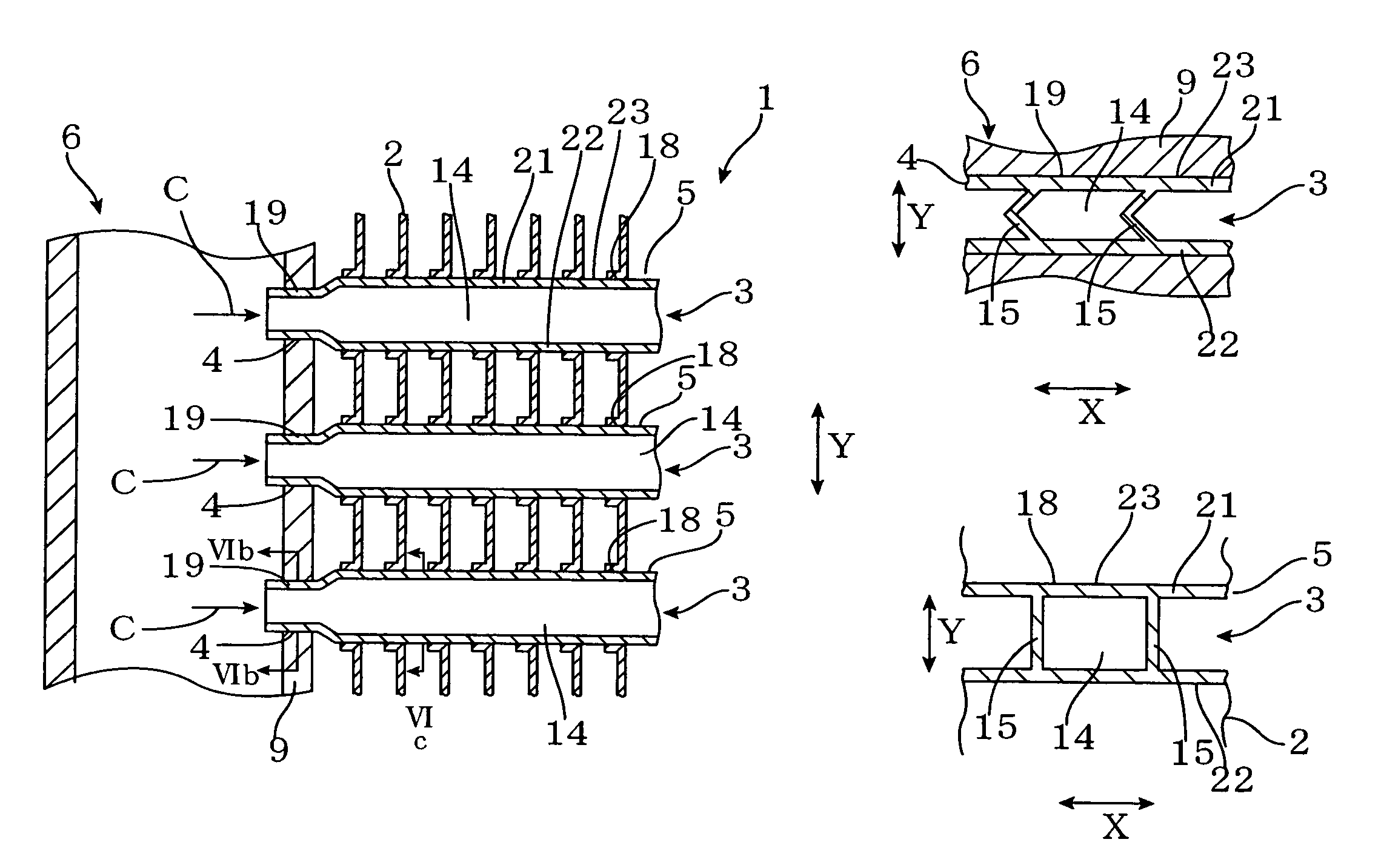
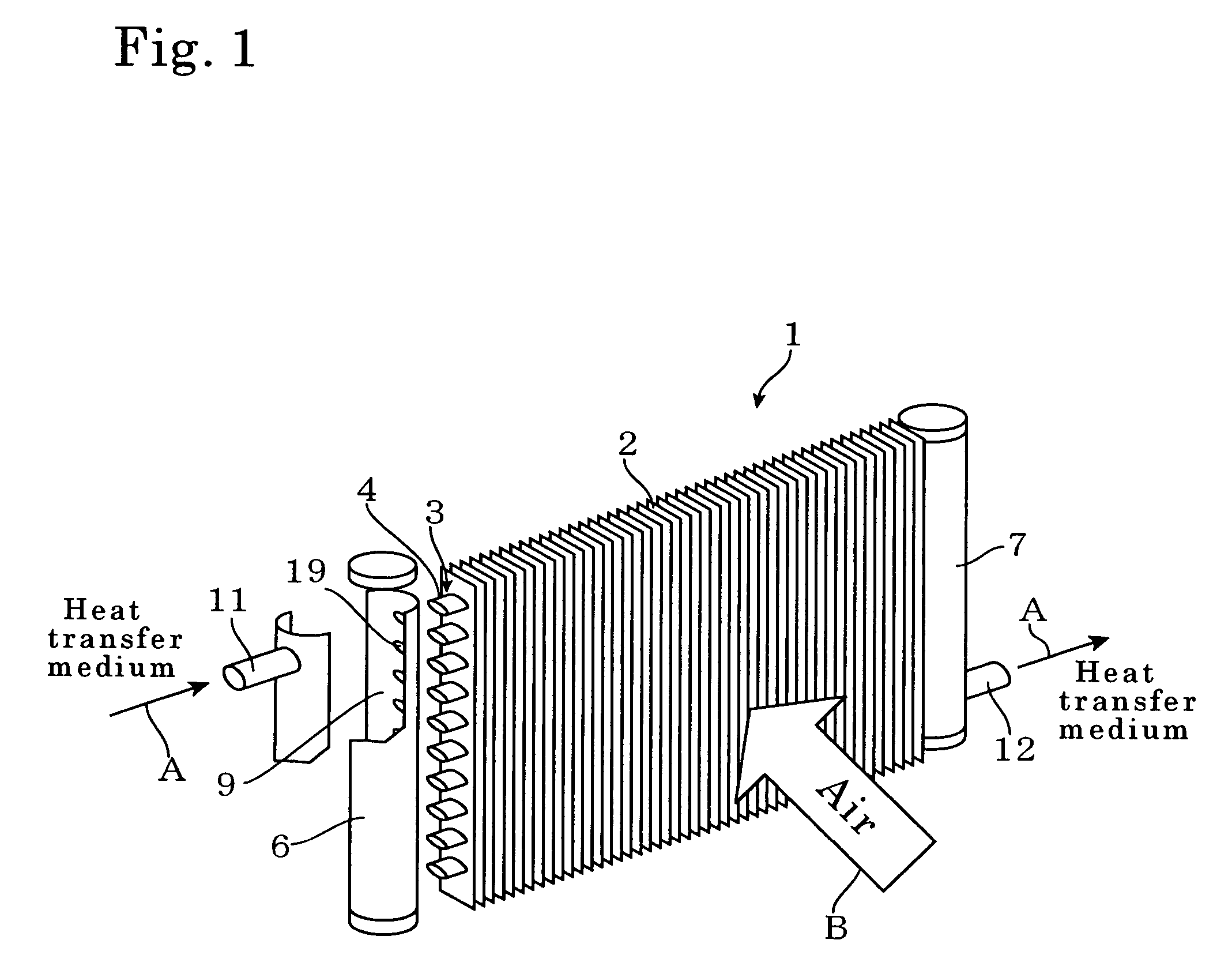
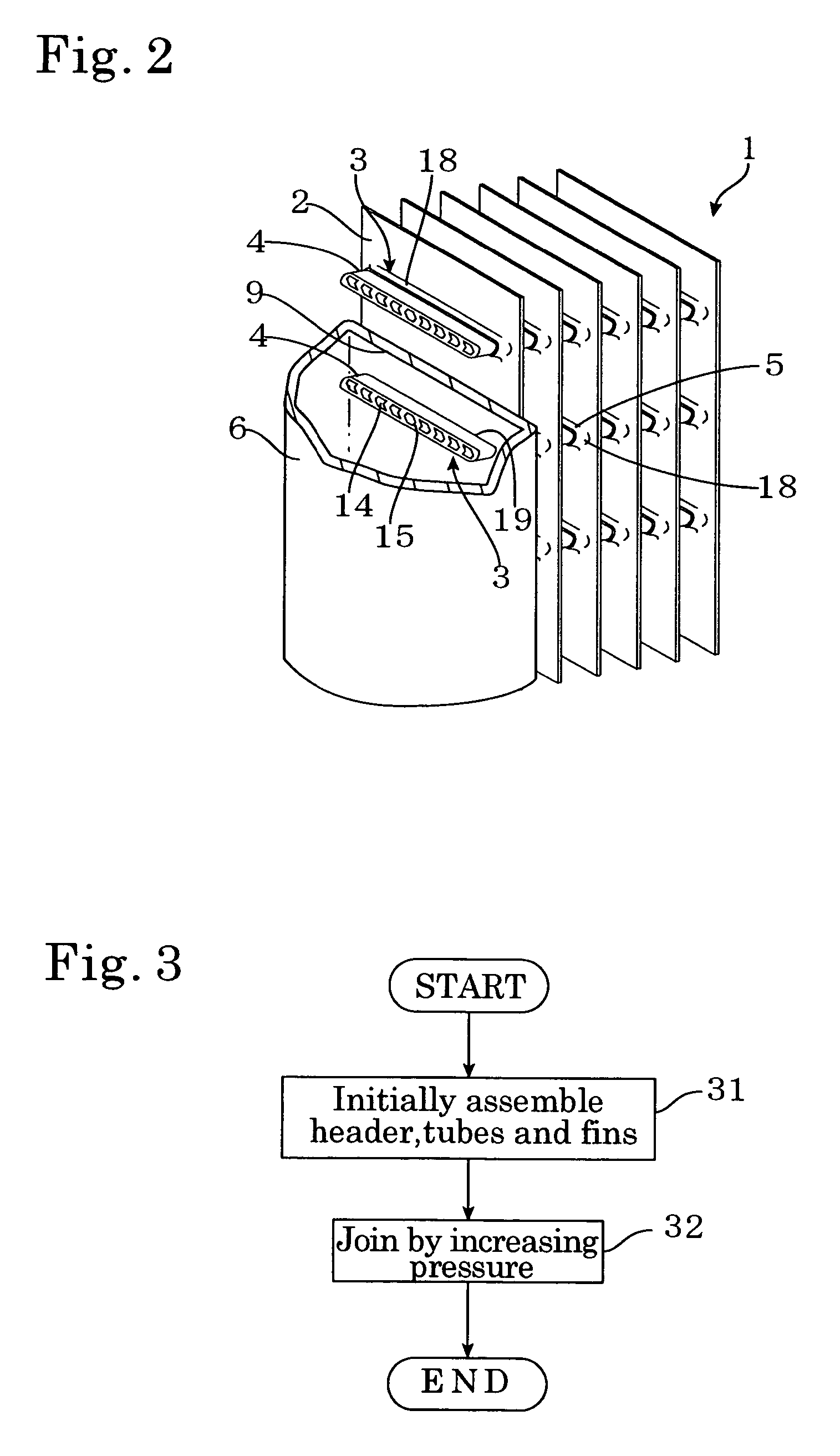
[0036]The present invention will now be described in more detail with reference to the drawings. FIG. 1 is a schematic diagram showing a heat exchanger according to the present invention. FIG. 2 is an expanded view of a state where a header, tubes (flat tubes in the present embodiment), and fins of the heat exchanger 1 have been assembled. The heat exchanger 1 of the present embodiment is a plate fin-type heat exchanger and has a plurality of plate-type fins 2 disposed in parallel with fixed gaps in between and a plurality of flat tubes 3 that are attached to the fins 2 in a state where the flat tubes 3 pass through the fins 2 in parallel. These flat tubes 3 are flat multi-channeled tubes (multi-channel flat tube) whose insides are divided into a plurality of parallel flow channels by a plurality of partitions. End parts 4 at both ends of the flat tubes 3 are connected to joining holes 19 formed in side walls 9 of headers 6 and 7 positioned on the left and the right so that a heat t...


PUM

PropertyMeasurementUnit
internal diameteraaaaaaaaaa
pressureaaaaaaaaaa
internal diameteraaaaaaaaaa

Abstract

There is provided a method of manufacturing a heat exchanger, including a first step of mounting an end part of flat tube to a header, assembling the flat tube and fins, and sealing a part where the header and the end part is attached, and a second step of increasing an internal pressure of the flat tube to expand other part of flat tubes aside from the end parts with respect to the end part of the tube in order to make the fins and the other part of the flat tube in contact each other. According to this method of manufacturing, in the second step, the other part of the flat tube that passes through the fins is expanded, so that it is possible to mechanically join the flat tube and the fins, and a plate fin-type heat exchanger with high strength and heat exchange efficiency can be easily provided.

Description

TECHNICAL FIELD[0001]The present invention relates to a heat exchanger that is used in a refrigeration apparatus and others, and a method of manufacturing the heat exchanger.RELATED ART[0002]Heat exchangers used in refrigeration apparatuses, radiators, or the like, including plate fins having a plate-like form or corrugated fins having a wave-like form are known. A heat exchanger 100 shown in FIG. 15 is a plate fin-type heat exchanger including a plurality of plate fins 110 that are disposed in parallel with fixed intervals and a plurality of tubes 120 disposed so as to pass through the fins 110. By causing a heat exchanging fluid A, such as a refrigerant, to flow through the pipes or tubes 120, heat exchange is conducted between the fluid A and a fluid B, such as air, that flows outside the heat exchanger. In the manufacturing process of this plate fin-type heat exchanger 100, a rigid rod or a tube expander presses out and expands the individual tubes inserted in the fins 110 mecha...

Claims


Application Information

Patent Timeline
Patent Type & Authority Patents(United States)
IPC IPC(8): F28F9/04B21D39/06B21D53/08B23P15/26F28D1/053F28F1/02F28F1/32F28F9/18
CPCB21D39/06B21D53/08B23P15/26F28D1/05366F28D1/05383F28F1/022F28F17/005F28F1/32Y10T29/49375F28F9/18F28F2275/125Y10T29/49373Y10T29/4938Y10T29/4935
Inventor TSUJI, MASANORIMAEZAWA, TAKAHIDE
Owner DENSO AIRCOOL CORP
Learn More