Vehicle body floor structure

a vehicle body and floor technology, applied in the direction of roofs, transportation and packaging, vehicle arrangements, etc., can solve the problems of inability to achieve enhanced aerodynamic performance, unfavorable ground height of the vehicle, and difficulty in achieving enhanced aerodynamic performance, etc., to achieve enhanced efficiency and enhanced aerodynamic performance of the vehicle floor

Active Publication Date: 2009-03-10
HONDA MOTOR CO LTD
View PDF3 Cites 56 Cited by
  • Summary
  • Abstract
  • Description
  • Claims
  • Application Information

AI Technical Summary

Benefits of technology

[0008]In view of the foregoing prior art problems, it is a first object of the present invention to provide an improved vehicle body floor structure which can receive a side collision impact with an enhanced efficiency and achieve an enhanced aerodynamic performance of the vehicle floor.
[0009]It is a second object of the present invention to provide an improved vehicle body floor structure which can increase an inner space of the vehicle compartment, can be reduced in weight and can achieve an enhanced aerodynamic performance of the vehicle floor.

Problems solved by technology

However, the side collision impact dispersion capability of the disclosed vehicle body floor structure 201 is not sufficient, and thus, the disclosed vehicle body floor structure has a room for further improvement.
However, if the in-vehicle space is to be increased, the vehicle body floor structure disclosed in the No. 3434199 publication would present the problem that the height of the floor frame 224 and hence the ground height of the vehicle (from the ground surface) has to be lowered.
Further, because the left and right forwardly-extending reinforcing members 226 and reinforcing gussets 227 are provided on the left and right sides of the vehicle floor, the weight of the disclosed vehicle body floor structure would undesirably increase to a considerable degree.
Furthermore, because an airstream flowing under the floor panel 223 during travel of the vehicle (traveling air) interferes with the floor frames 224, it is difficult to achieve an enhanced aerodynamic performance.

Method used


Image

  • Vehicle body floor structure
  • Vehicle body floor structure
  • Vehicle body floor structure

Examples


first embodiment

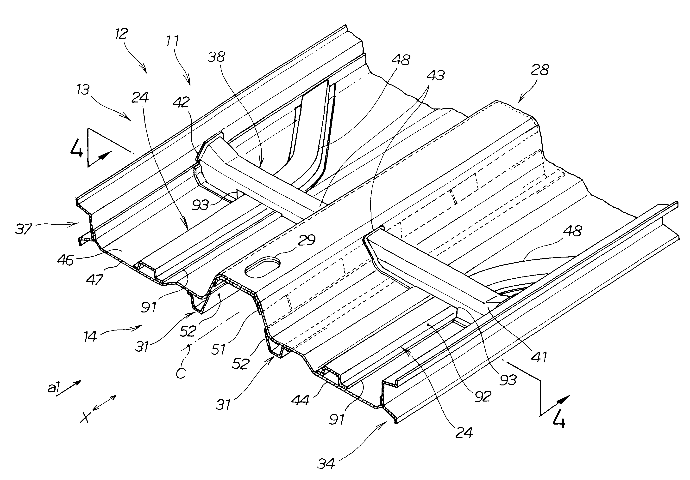
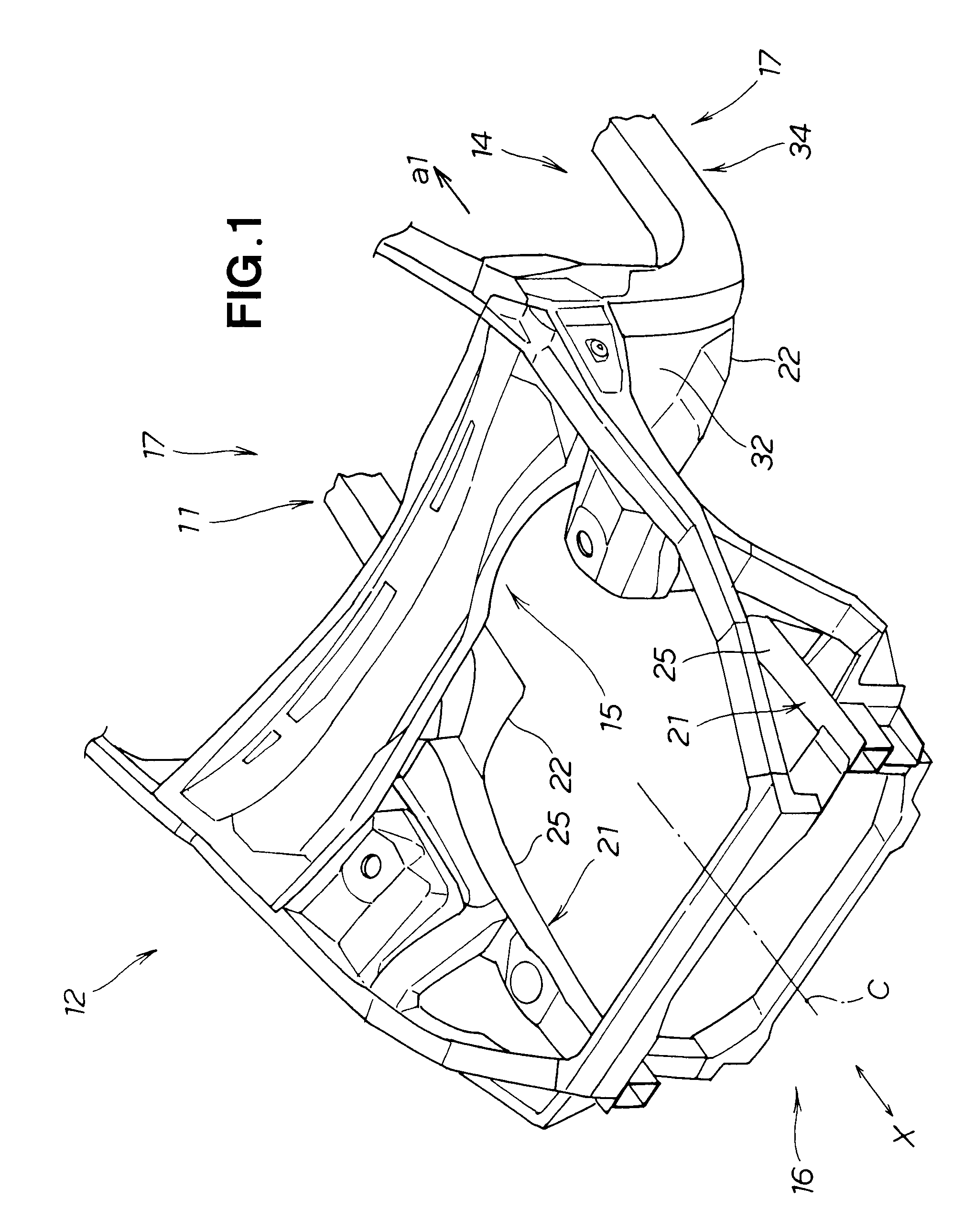
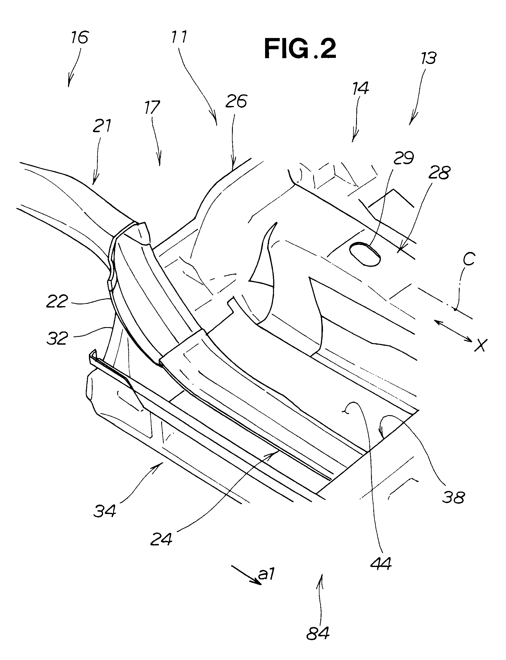
[0039]Reference is now made to FIG. 1 showing in perspective a front body connecting to a vehicle body floor structure 11 according to the present invention and FIG. 2 showing in perspective a front floor frame 24 connecting to the vehicle body floor structure 11.

[0040]The vehicle body floor structure 11 is employed in a floor body 14 that constitutes a floor of a compartment 13 of a vehicle 12; details of the vehicle body floor structure 11 will be discussed later.

[0041]The vehicle 12 includes the floor body 14 constituting the floor, left and right side bodies 17 that constitute side walls of the vehicle compartment 13, a front body 16 disposed in front of the vehicle compartment 13, and a dashboard 15 that constitutes a wall separating the front body 16 from the vehicle compartment 13. The left and right side bodies 17 include left and right side sills 34 and 37 (FIG. 3) joined to the left and right sides of the floor body 14.

[0042]The front body 16 includes left and right front ...

second embodiment

[0060]FIG. 10 is a perspective view showing details of left and right rear sections of the vehicle body floor structure shown in FIG. 6. the vehicle body floor structure includes left and right intersecting joint sections 62 each formed by the aforementioned front floor frame 24 and floor cross member 38 being joined with each other in an intersecting fashion. In each of the intersecting joint sections 62, the floor cross member 38 strides over the front floor frame 24, and the front floor frame 24 has one end fixedly joined to the side sill 34 or 37 provided at a lower end portion of the left or right side body 17 and the other end fixedly joined to the tunnel section 28.

[0061]FIG. 11 is a view taken in a direction of arrow A11 of FIG. 10, FIG. 12 is a view taken in a direction of arrow A12 of FIG. 10, and FIG. 13 is a view taken in a direction of arrow A13 of FIG. 10.

[0062]The floor cross member 38 has a sectional shape of a channel or groove and extends in the width (Y-axis) dire...


PUM


Abstract

A vehicle body floor structure includes: a floor panel; a floor cross member provided on the floor panel and joined to left and side sills provided on left and right sides of the floor panel; and left and right front floor frames provided on the floor panel and extending from a dashboard cross member to a substantial middle region of the floor panel through a recessed portion of the floor cross member. The left and right front floor frames each have a rear section located rearwardly of the floor cross member, and these rear sections are bent outwardly to be joined to the left and right side sills, respectively. Each of the front floor frames may be provided on the upper surface of a downwardly concaved floor section of the floor panel and extend between the concaved floor section and the floor cross member.

Description

FIELD OF THE INVENTION[0001]The present invention relates to a vehicle body floor structure capable of appropriately responding to a lateral or side collision impact (i.e., impact caused by a side collision of the vehicle). The present invention also relates to a vehicle body floor structure capable of appropriately responding to a frontal collision impact.BACKGROUND OF THE INVENTION[0002]The conventionally-known vehicle body floor structures have a function for dealing with a side collision impact and are provided with a floor cross member disposed under front seats and extending in a left-right or width direction of the vehicle body, as disclosed for example in Japanese Patent Application Laid-Open Publication No. 2005-119492.[0003]FIGS. 16A and 16B are views explanatory of the conventional vehicle body floor structure disclosed in the 2005-119492 publication. The disclosed vehicle body floor structure 201 includes: left and right side sills provided on left and right sides of a v...

Claims


Application Information

Patent Timeline
Patent Type & Authority Patents(United States)
IPC IPC(8): B60J7/00
CPCB62D21/157B62D25/2036B62D35/02B62D25/025Y02T10/88
Inventor ABE, YOSHIOONODA, YASUNOBUTOBA, YOSHIYUKI
Owner HONDA MOTOR CO LTD
Why Eureka
Try Eureka