
Methods and apparatuses for analyzing polynucleotide sequences

a polynucleotide sequence and analysis method technology, applied in the field of high speed, high throughput analysis of polynucleotide sequences, can solve the problems of time-consuming process, numerous disadvantages of the above-mentioned methods, and apparatuses used in these methods are not truly automatic sequencers

Inactive Publication Date: 2009-03-10
CALIFORNIA INST OF TECH
View PDF191 Cites 450 Cited by
  • Summary
  • Abstract
  • Description
  • Claims
  • Application Information

AI Technical Summary

Benefits of technology

This approach enables faster and more efficient DNA sequencing with reduced reagent use, improved accuracy, and the ability to analyze longer sequences simultaneously, overcoming the limitations of traditional methods by minimizing reagent exchange time and misincorporation.

Problems solved by technology

However, all these methods still require separation of DNA products by a gel permeation procedure and then detection of their locations relative to one another along the axis of permeation or movement through the gel.
These apparatuses used in these methods are not truly automatic sequencers.
The disadvantages of the above methods are numerous.
The most serious problems are caused by the requirement for the DNA fragments to be size-separated on a polyacrylamide gel.
This process is time-consuming, uses large quantities of expensive chemicals, and severely limits the number of bases which can be sequenced in any single experiment, due to the limited resolution of the gel.
While the basic scheme in these methods no longer require separation of polynucleotides on the gel, they encounter various other problems such as consumption of large amounts of expensive reagents, difficulty in removing reagents after each step, misincorporation due to long exchange times, the need to remove labels from the incorporated nucleotide, and difficulty to detect further incorporation if the label is not removed.
Many of these difficulties stem directly from limitations of the macroscopic fluidics employed.
However, small-volume fluidics have not been available.
As a result, these methods have not replaced the traditional gel-based sequencing schemes in practice.

Method used


Image

  • Methods and apparatuses for analyzing polynucleotide sequences
  • Methods and apparatuses for analyzing polynucleotide sequences
  • Methods and apparatuses for analyzing polynucleotide sequences

Examples


example 1

PDMS-DAPEG-PEM Surface Chemistry

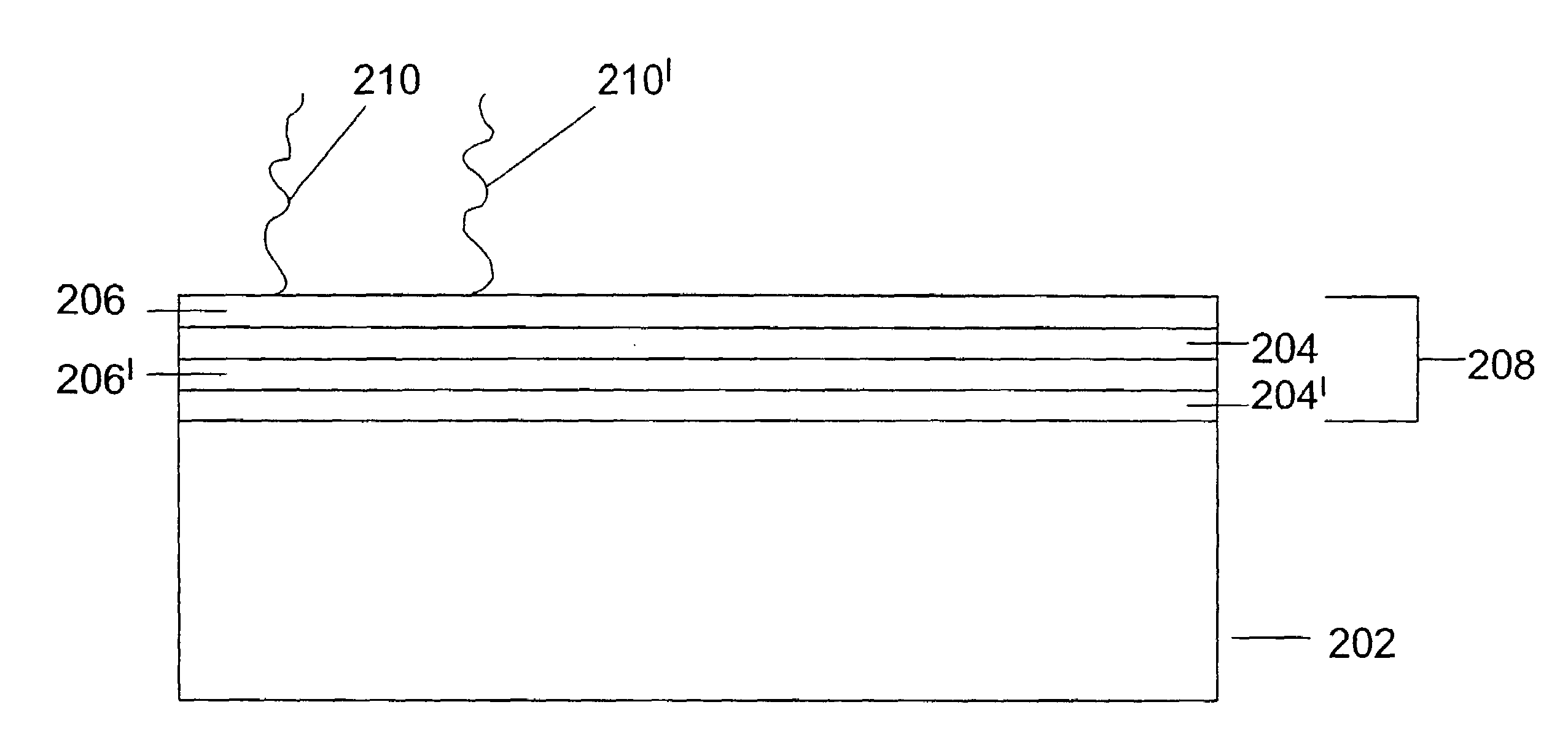
[0232]This set of experiments demonstrates a non-UV-based, specific and tunable anchoring of DNA to poly(dimethylsiloxane) (PDMS) in which the DNA remains sterically available for enzymatic biochemical reactions and fluorescence background from non-specific binding is suppressed through polyelectrolyte multilayer (PEM) surface chemistry. In general terms, these experiments utilize a microfluidic chip having a PDMS layer as a floor for the flow channels, and PEM linked to the PDMS with diacrylated poly(ethylene glycol) (DAPEG).

Microfluidic Chip Fabrication

[0233]PDMS microfluidic chips with integrated micromechanical valves were built using soft lithography as described herein with the following modifications. Silicon wafers were exposed to hexamethyldisilazane (HMDS) (ShinEtsuMicroSi, Phoenix, Ariz.) vapors for 3 minutes. Photoresist 5740 (MicroChem Corp., Newton, Mass.) was spun at 2500 rpm for 60 seconds on a Model WS-400A-6NPP / LITE spinner from Laur...

example 2

Multiplexor Method

[0250]According to one aspect of the invention, the number of chambers can be increased to increase the total read length by the same factor. FIG. 31 shows the layout of a multiplexor device comprising 16 chambers (316, 316′, 316″). During the interrogation step, sequencing is conducted through the multiplexor in a single chamber as described above. Once a base is determined, the primers in all chambers are built up to that base by feeding the conjugate standard nucleotides and polymerase down the main channel (322). Alternating between interrogation and buildup produces total read length equal to number of chambers times the read length per single chamber. In addition, the independence of buildup and interrogation feeds means that different polymerases can be used for each feed (for example, more promiscuous and less-sterically-sensitive ones for interrogation, and stricter ones for buildup).

[0251]In another embodiment, the read length can be doubled in an array o...


PUM

PropertyMeasurementUnit
widthaaaaaaaaaa
thicknessaaaaaaaaaa
heightaaaaaaaaaa

Abstract

Methods for high speed, high throughput analysis of polynucleotide sequences, and apparatuses with which to carry out the methods are provided in the invention.

Description

REFERENCE TO OTHER APPLICATIONS[0001]This non-provisional patent application claims the benefit of U.S. Provisional Application No. 60 / 526,162, filed Dec. 1, 2003 and is a continuation-in-part of U.S. patent application Ser. No. 09 / 908,830 filed Jul. 18, 2001, now U.S. Pat. No. 6,818,395, which is a divisional of U.S. patent application Ser. No. 09 / 707,737 filed Nov. 6, 2000, which claimed the benefit of U.S. provisional patent application No. 60 / 163,742 filed Nov. 4, 1999 and was a continuation-in-part of U.S. patent application Ser. No. 09 / 605,520 filed Jun. 27, 2000, which in turn claims the benefit of U.S. provisional patent application No. 60 / 141,503 filed Jun. 28, 1999, U.S. provisional patent application No. 60 / 147,199 filed Aug. 3, 1999, and U.S. provisional patent application No. 60 / 186,856 filed Mar. 3, 2000. Reference is also made to U.S. non-provisional application Ser. No. 11 / 002,739 filed on Dec. 1, 2004, by Quake et al. The text of each of the foregoing patent applica...

Claims


Application Information

Patent Timeline
Patent Type & Authority Patents(United States)
IPC IPC(8): C12Q1/68
CPCB01L3/502707B01L3/50273B01L3/502738B82Y30/00C12Q1/6869B01J2219/00398B01J2219/00432B01J2219/00497B01J2219/00527B01J2219/00605B01J2219/0061B01J2219/00612B01J2219/00621B01J2219/00626B01J2219/00628B01J2219/0063B01J2219/00632B01J2219/00635B01J2219/00637B01J2219/00659B01J2219/00722B01L3/5027B01L2300/0816B01L2300/0867B01L2300/123B01L2400/0481B01L2400/0655C12Q2565/629C12Q1/68
Inventor QUAKE, STEPHENKARTALOV, EMIL PASKALEV
Owner CALIFORNIA INST OF TECH
Learn More