
Plasma display device and plasma display panel driving method

a technology of plasma display panel and display device, which is applied in the direction of gas discharge electrodes, identification means, instruments, etc., to achieve the effect of convenient use, low gray representation, and excellent performan

Inactive Publication Date: 2009-03-10
SAMSUNG SDI CO LTD
View PDF6 Cites 2 Cited by
  • Summary
  • Abstract
  • Description
  • Claims
  • Application Information

AI Technical Summary

Benefits of technology

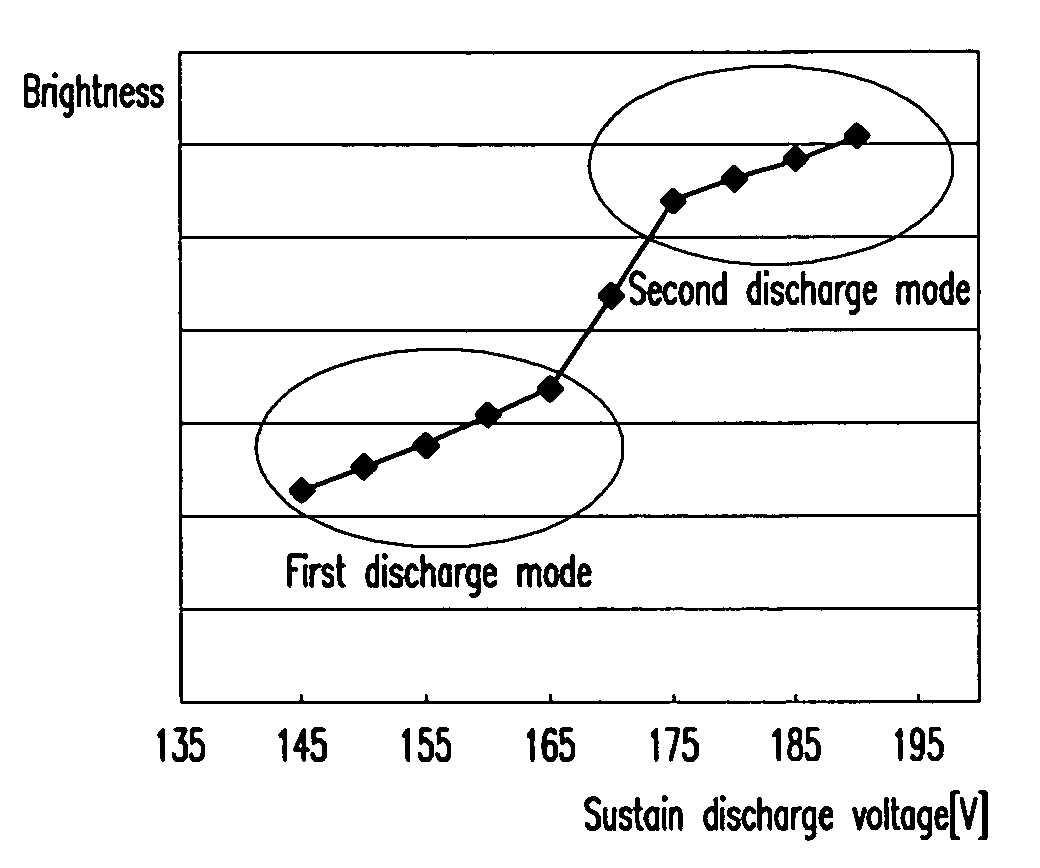
The present invention provides a plasma display device with excellent performance of low gray representation and a PDP driving method to facilitate the same. The device uses a low sustain discharge voltage in a subfield with a low weight. The method includes dividing a frame into a plurality of subfields with different weights, driving them, and alternately applying sustain discharge pulses to the first and second electrodes in a sustain period. The first electrode includes a first bus electrode and a first region formed within the discharge cell, and the second electrode includes a second bus electrode and a second region formed within the discharge cell. The width of the second region towards the direction of the first bus electrode is narrower than the length of the first region towards the direction of the first bus electrode. The discharge mode by the sustain discharge pulse in at least one subfield is different from the discharge mode in another subfield.

Problems solved by technology

Since the DC PDPs have electrodes exposed in the discharge space, they allow a current to flow in the discharge space while the voltage is supplied, and therefore they are problematic in that they require resistors for current restriction.

Method used


Image

  • Plasma display device and plasma display panel driving method
  • Plasma display device and plasma display panel driving method
  • Plasma display device and plasma display panel driving method

Examples


Embodiment Construction

[0033]In the following detailed description, only certain exemplary embodiment(s) of the present invention are shown and described, simply by way of illustration. As those skilled in the art would realize, the described embodiment may be modified in various different ways, all without departing from the spirit or scope of the present invention. Accordingly, the drawings and description are to be regarded as illustrative in nature, and not restrictive.

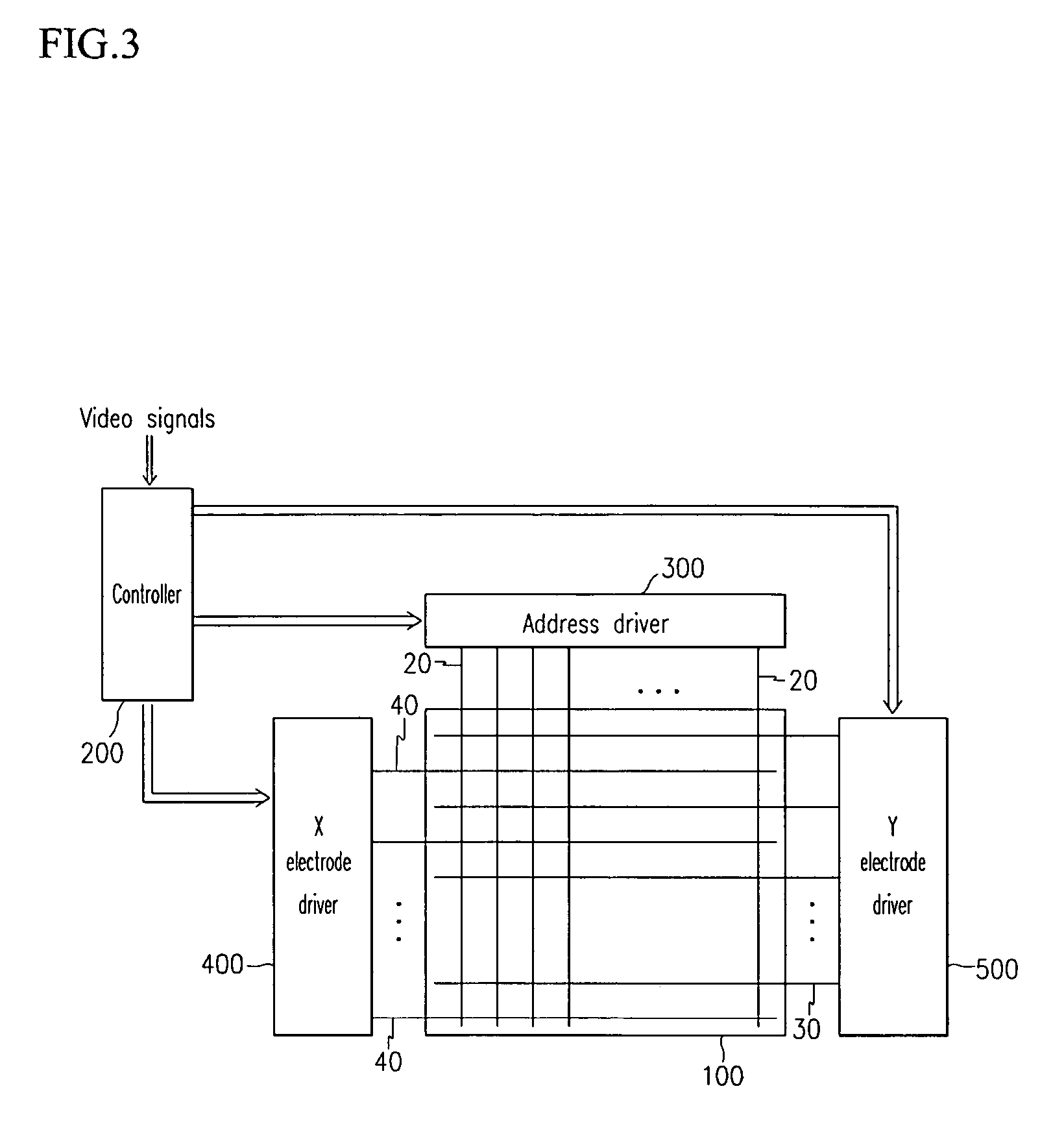
[0034]FIG. 3 shows a brief conceptual diagram of a plasma display device according to an exemplary embodiment of the present invention.

[0035]As shown in FIG. 3, the plasma display device includes a PDP 100, a controller 200, an address driver 300, an X (or sustain) electrode driver 400, and a Y (or scan) electrode driver 500. The X electrode driver 400 and the Y electrode driver 500 are separately provided in FIG. 3, but they can also be combined into a single unit.

[0036]The PDP 100 includes a plurality of address electrodes 20 provided...


PUM


Abstract

A plasma display panel (PDP) that has a T-shaped electronic structure or an electrode structure with adjacent parts of the scan electrode and the sustain electrode being broad, and parts coupled to the bus electrodes being narrow in a like manner to the T-shaped electrode structure is provided. The PDP has various discharge modes according to magnitudes of sustain discharge voltages. A frame is divided into a plurality of subfields with respective weights and is driven in the PDP. The subfields with low weights use low sustain discharge voltages to perform a discharge with a small quantity of emitting light, and the subfields with high weights use high sustain discharge voltages to perform a discharge with a big quantity of emitting light, thereby increasing representation performance of low gray scales.

Description

CROSS REFERENCE TO RELATED APPLICATION[0001]This application claims priority to and the benefit of Korea Patent Application No. 2003-74641 filed on Oct. 24, 2003 in the Korean Intellectual Property Office, the entire content of which is incorporated herein by reference.BACKGROUND OF THE INVENTION[0002](a) Field of the Invention[0003]The present invention relates to a plasma display device and a plasma display panel (PDP) driving method.[0004](b) Description of the Related Art[0005]A PDP is a flat display that uses plasma generated via a gas discharge process to display characters or images. Depending on its size, the PDP can include tens to millions of pixels that are provided thereon in a matrix format. According to the supplied driving voltage waveforms and discharge cell structures, PDPs can be categorized into direct current (DC) PDPs and alternating current (AC) PDPs.[0006]Since the DC PDPs have electrodes exposed in the discharge space, they allow a current to flow in the disc...

Claims


Application Information

Patent Timeline
Patent Type & Authority Patents(United States)
IPC IPC(8): G09G3/28G09F9/313H01J17/04H01J17/49
CPCG09G3/2011G09G3/294G09G2300/0426G09G2320/0238G09G3/296H01J11/22
Inventor HEO, EUN-GI
Owner SAMSUNG SDI CO LTD
Learn More