Powder filling method, powder filling device, and powder filling nozzle

a filling device and filling nozzle technology, applied in the direction of liquid handling, packaging goods type, transportation and packaging, etc., can solve the problems of affecting the work of toner filling, affecting the original function of increasing the and removing or losing the original function of increasing fluidity by external additives

Inactive Publication Date: 2009-03-17
RICOH KK
View PDF27 Cites 7 Cited by
  • Summary
  • Abstract
  • Description
  • Claims
  • Application Information

AI Technical Summary

Benefits of technology

[0028]A general object of the present invention is to provide an improved powder filling method in which the above-mentioned problems are eliminated.
[0029]A more specific object of the present invention is to provide a powder filling device and method which makes it possible to realize control which stops the delivery of the powder to the container instantly, without deteriorating the powder, and to fill up the container with the powder of the given quantity in a high-density state.
[0030]Especially the present invention aims at offering a powder filling nozzle which can solve the above-mentioned problems in the case of filling the container with the toner used for the development of an electrostatic latent image.
[0034]According to the present invention, the powder filling nozzle, powder filling device, and powder filling method which make it possible to fill up the container with the powder of a given amount in a high-density state efficiently and precisely.

Problems solved by technology

Furthermore, in the case of the auger type method, the external additive is buried in the toner, and the original function of increasing the fluidity by the external additive is eliminated or lost.
Moreover, in the case of the low-temperature fixing toner using a binding agent resin of a low melting point, the sticking of toner particles or aggregation is likely to occur since the toner is pressurized by rotation of the auger.
The problem that the toner filling work is interfered arises.
When the copying is performed with the developer in which the toner and the aggregation coexist, the quality of the reproduced image becomes inadequate since the aggregation has not a desired value of the electrostatic property.
Then, the necessity of discharging a large amount of gas existing in the powder particles will arise, and it is difficult to form the high-density filling state of the toner in the container.
Thus, the auger type method has the problem in that the arrangement of the toner filling device is fixed and several restrictions exist.
However, the proposed method requires a large-scale powder filling device in which the de-aeration piping is accurately disposed co-axially with the powder filling piping.
The manufacture of such powder filling device is difficult, and the weight becomes large.
When a small-diameter container or a container in which the internal wall of the container is configured in the shape of a spiral convex or others is used in order to facilitate the toner discharging, the delivery of the powder is prevented and mixing the powder in the container with the air is difficult.
Moreover, since the de-aeration of the powder is performed in the course of delivery of the powder to the container, the delivery of the powder is difficult.
Moreover, since the agitator is used to discharge the powder from the powder filling device, the separation of the external additive from the powder and the generation of aggregation will arise similar to the auger type method, and it is difficult to attain desired filling of the powder in the container.
However, the proposed method uses the auger type method, and the above-mentioned problems still remain unresolved.
When the external additive whose particle diameter is smaller than that of the powder is attracted through the filter layer, clogging of the filter layer may occur, and it is difficult to attain appropriate stopping function of the filter layer.
When the toner is supplied to the developing unit having a complicated structure directly, the filling state does not become uniform and the void is created so that the quality of the reproduced image becomes poor.
If that control cannot be performed enough, the powder is atomized around the powder filling device and the powder stain may occur.
Although the inventors adjusted the pressure open valve provided in the above-mentioned conventional powder fluidization unit and controlled the delivery pressure, it is found that the feature of stopping the powder flow into the container instantly is inadequate.
It is conceivable that the cause of the above problem is that, because a certain time for escaping the air from the pressure open valve is needed, the falling of the residual pressure takes some time and the distance from the powder fluidization unit to the container is too long.
It has been confirmed that the stop control of the powder filling is not performed adequately.
It is conceivable that the cause of the above problem is that the powder is pressurized by the mechanical stop unit.

Method used


Image

  • Powder filling method, powder filling device, and powder filling nozzle
  • Powder filling method, powder filling device, and powder filling nozzle
  • Powder filling method, powder filling device, and powder filling nozzle

Examples


Embodiment Construction

[0043]Before explaining a preferred embodiment of the invention, the powder fluidization unit for solving the above-mentioned problems in the toner filling method which is previously proposed by the inventors will be explained in order to make the understanding of the invention easy.

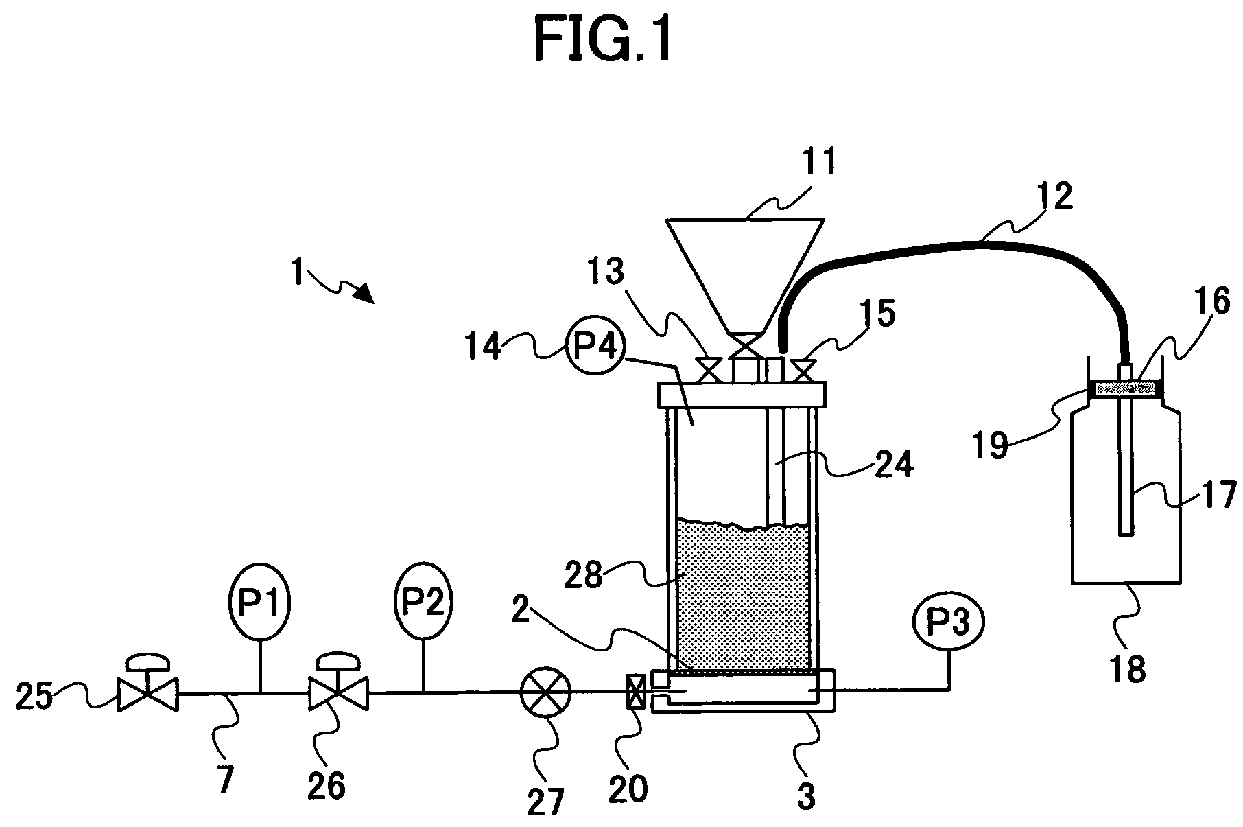
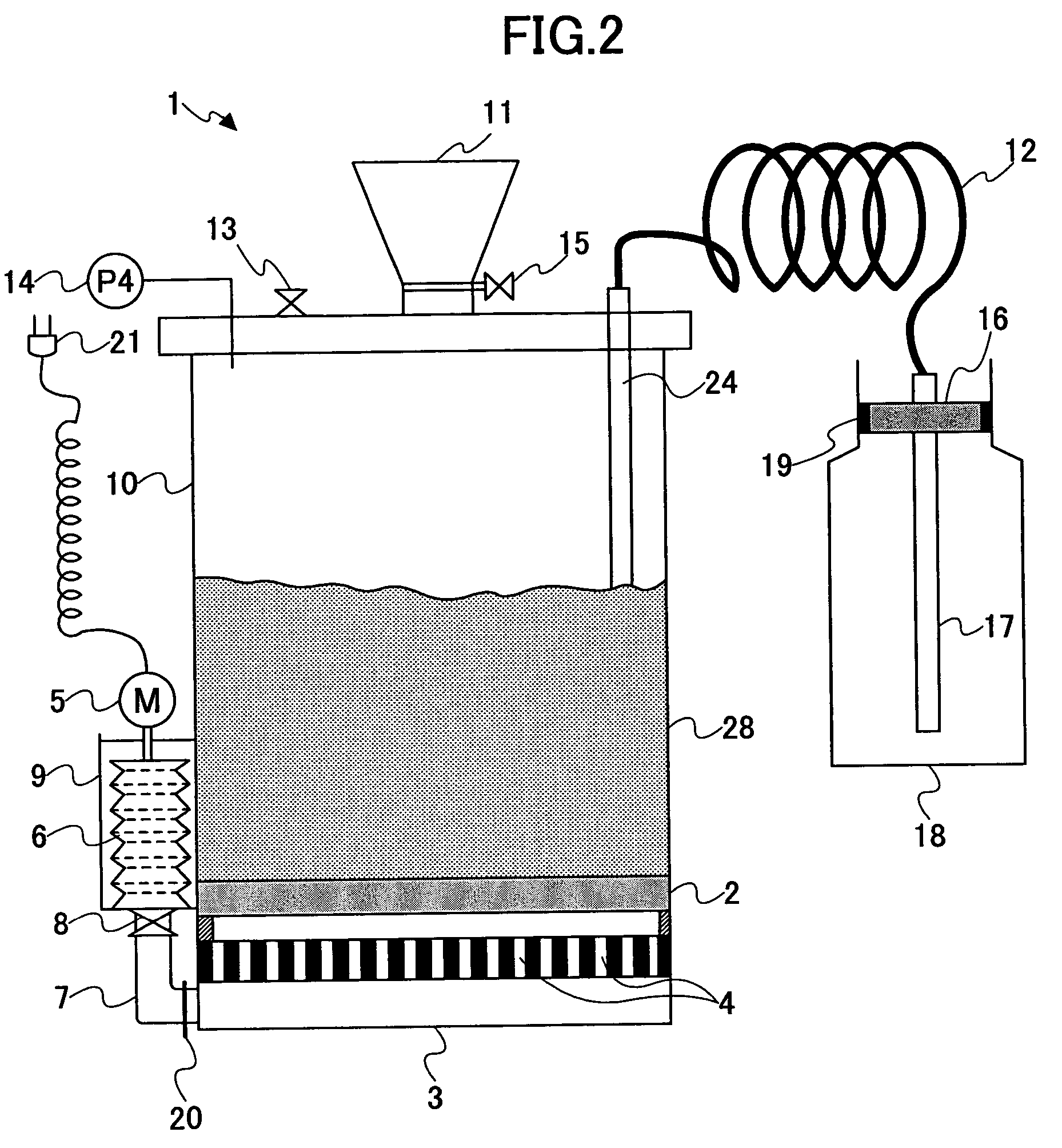
[0044]The proposed powder fluidization unit differs from the method of storing the powder into the container as in the auger type method in which the powder from the powder filling device is agitated and made to fall to the container. In this powder fluidization unit, a minimum quantity of gas is introduced uniformly into the powder within the powder fluidization unit, and a fluidized state of the powder is acquired. After that, the powder in the fluidized state is supplied by pressurization into the container separated from the powder fluidization unit so that the container is filled up with the powder.

[0045]The above-mentioned powder fluidization unit will be explained, together with the powder filling...


PUM

PropertyMeasurementUnit
gas suction pressureaaaaaaaaaa
particle sizeaaaaaaaaaa
volume particle diameteraaaaaaaaaa

Abstract

A powder filling nozzle is used for filling up a container with a powder mixed with a gas and in a fluidized state. The power filling nozzle comprises a tubular body having an opening for discharging the powder in the fluidized state into the container, and a gas separating unit disposed near the opening of the tubular body and allowing the gas delivered together with the powder in the tubular body to pass through the gas separating unit but not allowing the powder to pass through the gas separating unit. The gas separating unit serves to set the opening in a plugged state by the powder separated from the gas, so that the delivery of the powder from the tubular body into the container is stopped.

Description

TECHNICAL FIELD[0001]The present invention generally relates to the technology for filling up a container with minute powder represented by the toner for image formation by an electrophotographic printing system. In particular, the present invention relates to a powder filling method, a powder filling device, and a powder filling nozzle for efficiently filling powder into a small-inlet container or a small-capacity container the filling of which is difficult or impossible by a conventional system.BACKGROUND ART[0002]There are various types of powder filling methods for filling up a container with the powder, such as a toner for electrophotographic printing, which include a rotary valve type, a screw feeder type and an auger type. The fundamental concept of these methods is to drop the powder by its gravity from the powder filling device to the container disposed under the powder filling device, so that the container is filled up with the powder.[0003]Especially, the auger-type powde...

Claims


Application Information

Patent Timeline
Patent Type & Authority Patents(United States)
IPC IPC(8): B65B31/00B65B1/04B65B39/04
CPCB65B39/04
Inventor AMANO, HIROSATO
Owner RICOH KK
Why Eureka
Try Eureka