Vehicle braking system and vehicle braking method

a technology for vehicle braking and braking system, which is applied in the direction of braking system, electric device, braking components, etc., can solve the problem of difficulty in high-accuracy cooperative control, and achieve the effect of high accuracy and accurate monitoring

Inactive Publication Date: 2009-03-17
SUBARU CORP
View PDF15 Cites 14 Cited by
  • Summary
  • Abstract
  • Description
  • Claims
  • Application Information

AI Technical Summary

Benefits of technology

[0007]An object of one or more embodiments of the present invention is to perform a cooperative control of the friction braking and regenerative braking with high accuracy by accurately monitoring the regenerative braking force and friction braking force which are given to the wheel.

Problems solved by technology

As a result, it is difficult to perform the cooperative control with high accuracy.

Method used


Image

  • Vehicle braking system and vehicle braking method
  • Vehicle braking system and vehicle braking method
  • Vehicle braking system and vehicle braking method

Examples


first embodiment

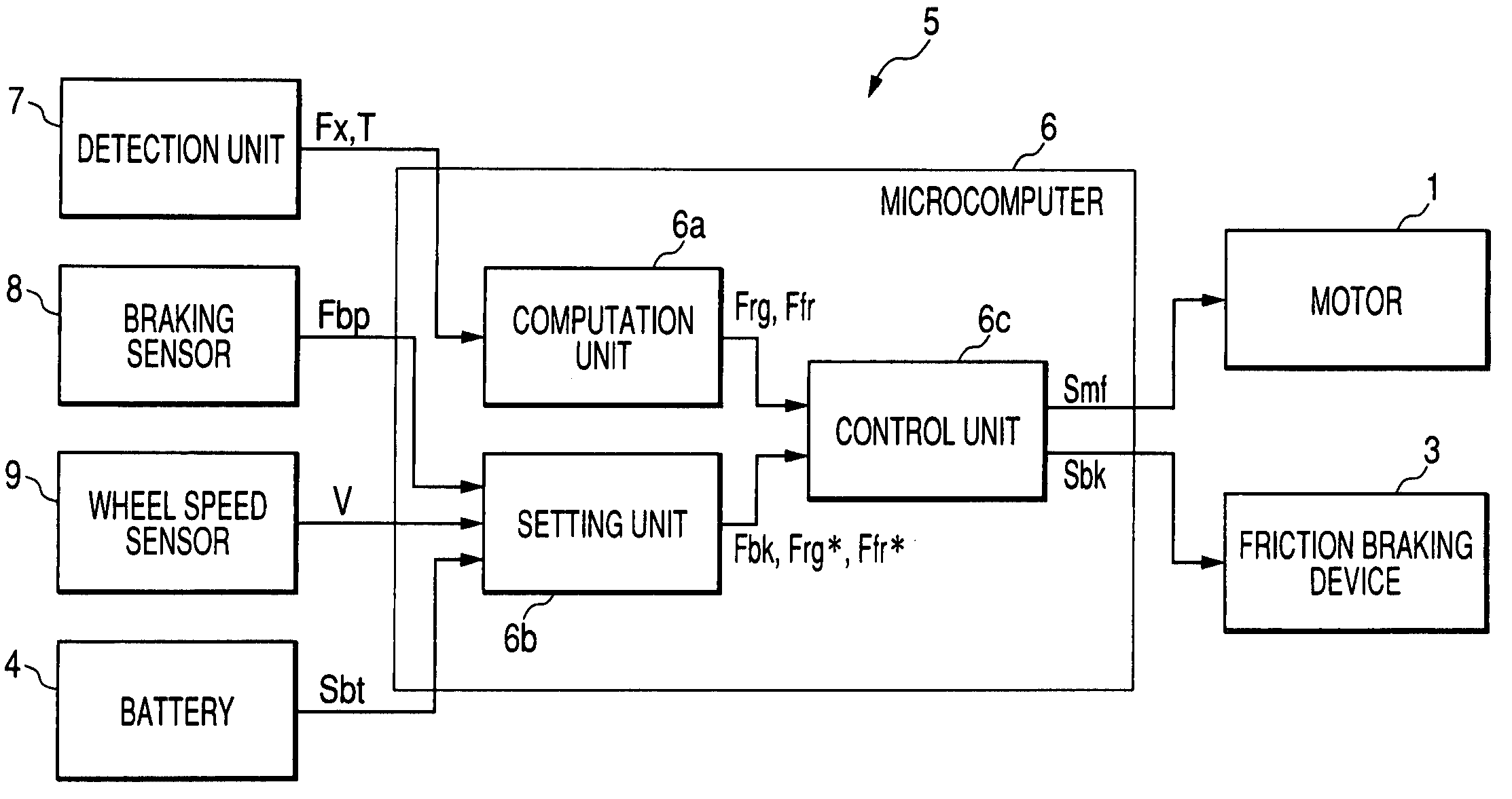
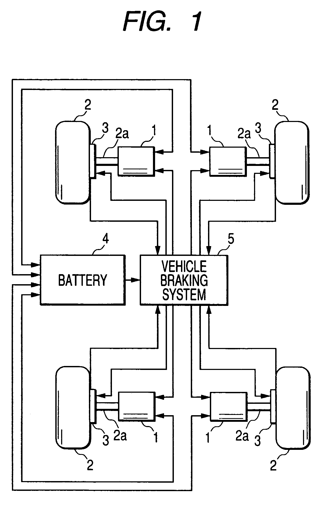
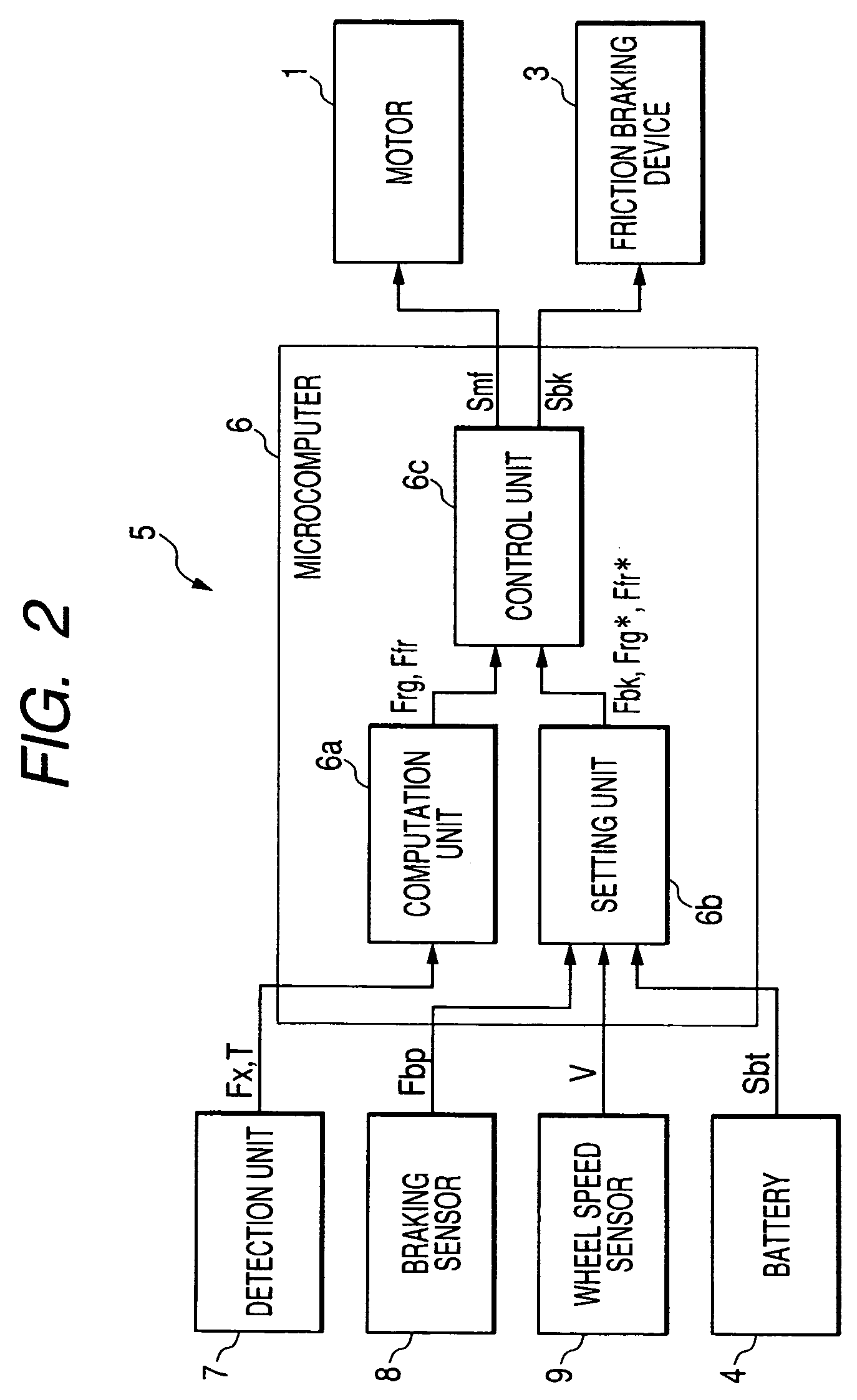
[0021]FIG. 1 is an explanatory drawing of a vehicle to which a vehicle braking system according to a first embodiment is applied. The vehicle is an electric vehicle with motors, each of motors drives each of wheels. That is, In the first embodiment, the vehicle drives all wheel by each motor corresponding to each wheel. Power from the motor 1 is transmitted to the wheel 2 via its own output shaft which corresponds to an axle 2a. When rotational torque is applied to the wheel 2 in association with such power transmission, the wheel 2 rotates, whereby a driving force is given to the wheel 2. A friction braking device 3 is provided on each wheel 2. Regarding friction braking device, there are two types of devices which are pneumatic and hydraulic friction braking devices, and these differ from each other in approaches to adjusting frictional force. In the first embodiment, hydraulic friction braking device which mainly includes a caliper, a disc rotor and brake pads is used in the firs...

second embodiment

[0038]FIG. 5 is an explanatory drawing of a vehicle to which a vehicle braking system according to a second embodiment is applied. The second embodiment differs from the first embodiment in that a plurality of wheels 2 are driven by a single motor. In the second embodiment, a single motor 1 is provided for four wheels 2. Note that in the following description, same reference numerals are given to the same constituent components to those of the first embodiment, and a detailed description thereof will be omitted.

[0039]Power from the motor 1 is transmitted to a center differential 10, and the power transmitted to the center differential 10 is then respectively transmitted to a front differential 11 provided on the side of front wheels and a rear differential 12 provided on the side of rear wheels. The center differential 10 is, for example, a compound planetary gear type differential. A hydraulic multi-disc clutch 13 having a function to limit its own differential movement is provided...


PUM


Abstract

A detection unit directly detects an operating force acting on a wheel. A computation unit respectively computes a current value of a regenerative braking force and a current value of a friction braking force based on the result of a detection by the detection unit. A setting unit sets a target value of the regenerative braking force and a target value of the friction braking force based on a required braking force. A control unit controls a regenerative braking device based on the current value of the regenerative braking force so that the regenerative braking force approaches to the target value and also controls a friction braking device based on the current value of the friction braking force so that the friction braking force approaches to the target value.

Description

CROSS REFERENCE TO RELATED APPLICATIONS[0001]The present application claims foreign priority based on Japanese Patent Application No. P.2004-161001, filed on May 31, 2004, the contents of which are incorporated herein by reference.BACKGROUND OF THE INVENTION[0002]1. Field of the Invention[0003]The present invention relates to a vehicle braking system and a vehicle braking method, and more particularly to vehicle braking that is effected using both a regenerative braking device and a friction braking device.[0004]2. Related Art[0005]In recent years, electric vehicles are known as friendly vehicles to the global environment. In general, in an electric vehicle, a motor is driven by electricity power supplied from a battery to thereby generate a driving force in a wheel. On the other hand, at the time of braking, the motor, which is a drive source, is used as a generator to convert kinetic energy into electric energy to thereby recover the energy. At the time of generation like this, a ...

Claims


Application Information

Patent Timeline
Patent Type & Authority Patents(United States)
IPC IPC(8): B60T8/64B60T8/17B60K7/00B60K17/356B60L7/10B60L7/24B60T1/10B60T8/00
CPCB60K7/0007B60K17/356B60L7/24B60T1/10B60W30/18127B60K2001/001B60K2007/0092B60L2220/44B60T2270/604B60W2300/18
Inventor TEZUKA, SYUNSUKE
Owner SUBARU CORP
Why Eureka
Try Eureka