Coaxial bi-modal imaging system for combined microwave and optical imaging

a combined microwave and optical imaging technology, applied in the direction of antenna details, instruments, antennas, etc., can solve the problems of inability to identify concealed weapons or other contraband, limited sensitivity of digital cameras, and inability to image opaque or concealed objects,

Active Publication Date: 2009-03-17
AGILENT TECH INC
View PDF46 Cites 16 Cited by
  • Summary
  • Abstract
  • Description
  • Claims
  • Application Information

AI Technical Summary

Problems solved by technology

However, digital cameras have limited sensitivity, and are not capable of imaging opaque or concealed items.
For example, at a point-of-entry into a facility, such as a government building, school, airport or other structure, traditional analog or digital cameras are not able to identify concealed weapons or other contraband (e.g., explosives).
However, in this configuration, the resulting optical and microwave images experience a parallax effect (shifting) due to the different focal points of the optical camera and the microwave transceiver, which increases the complexity of the image processing.
In addition, the mounting arms necessarily increase the size of the bi-modal imaging system, which may not be desirable in some situations.

Method used


Image

  • Coaxial bi-modal imaging system for combined microwave and optical imaging
  • Coaxial bi-modal imaging system for combined microwave and optical imaging
  • Coaxial bi-modal imaging system for combined microwave and optical imaging

Examples


Embodiment Construction

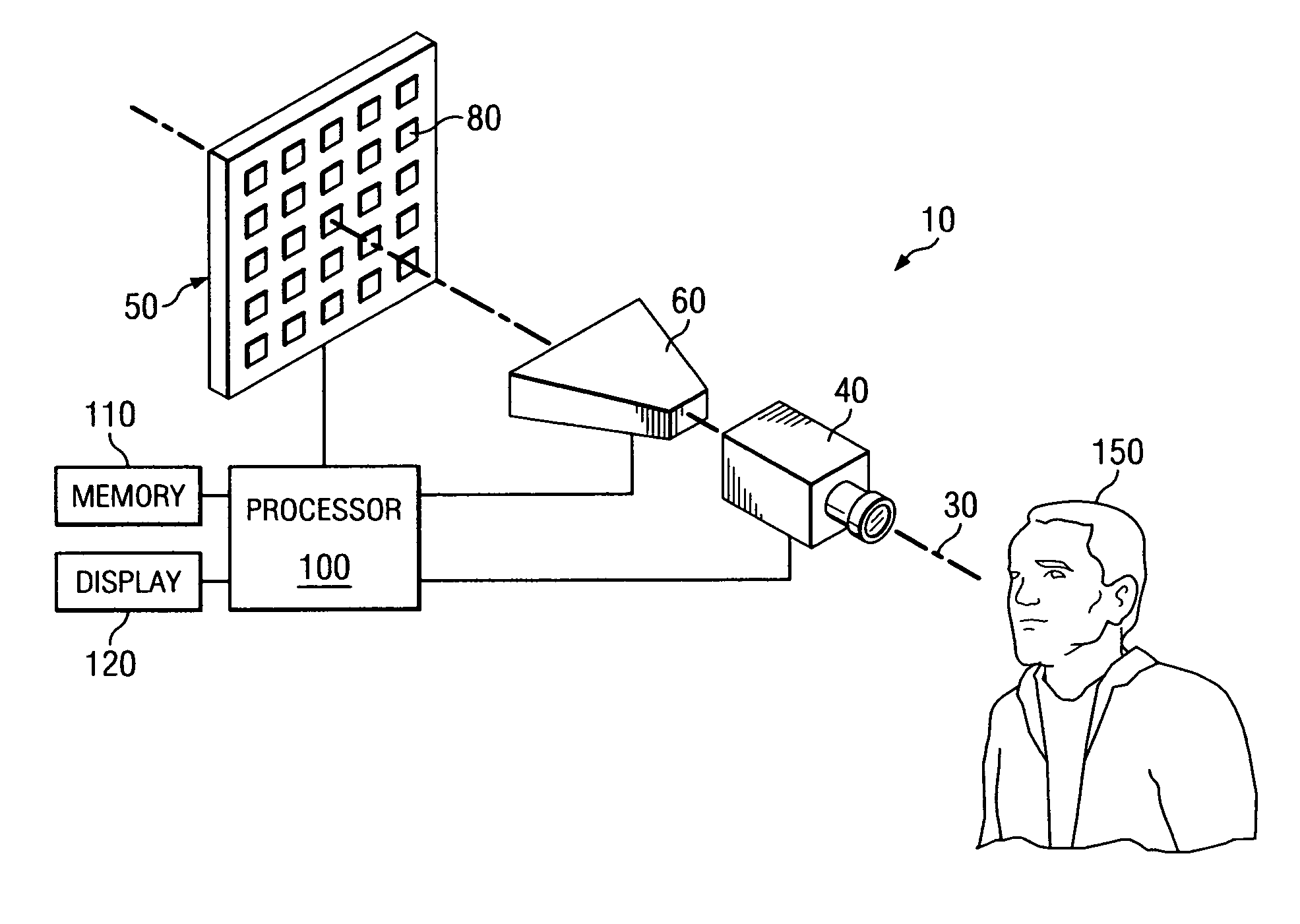
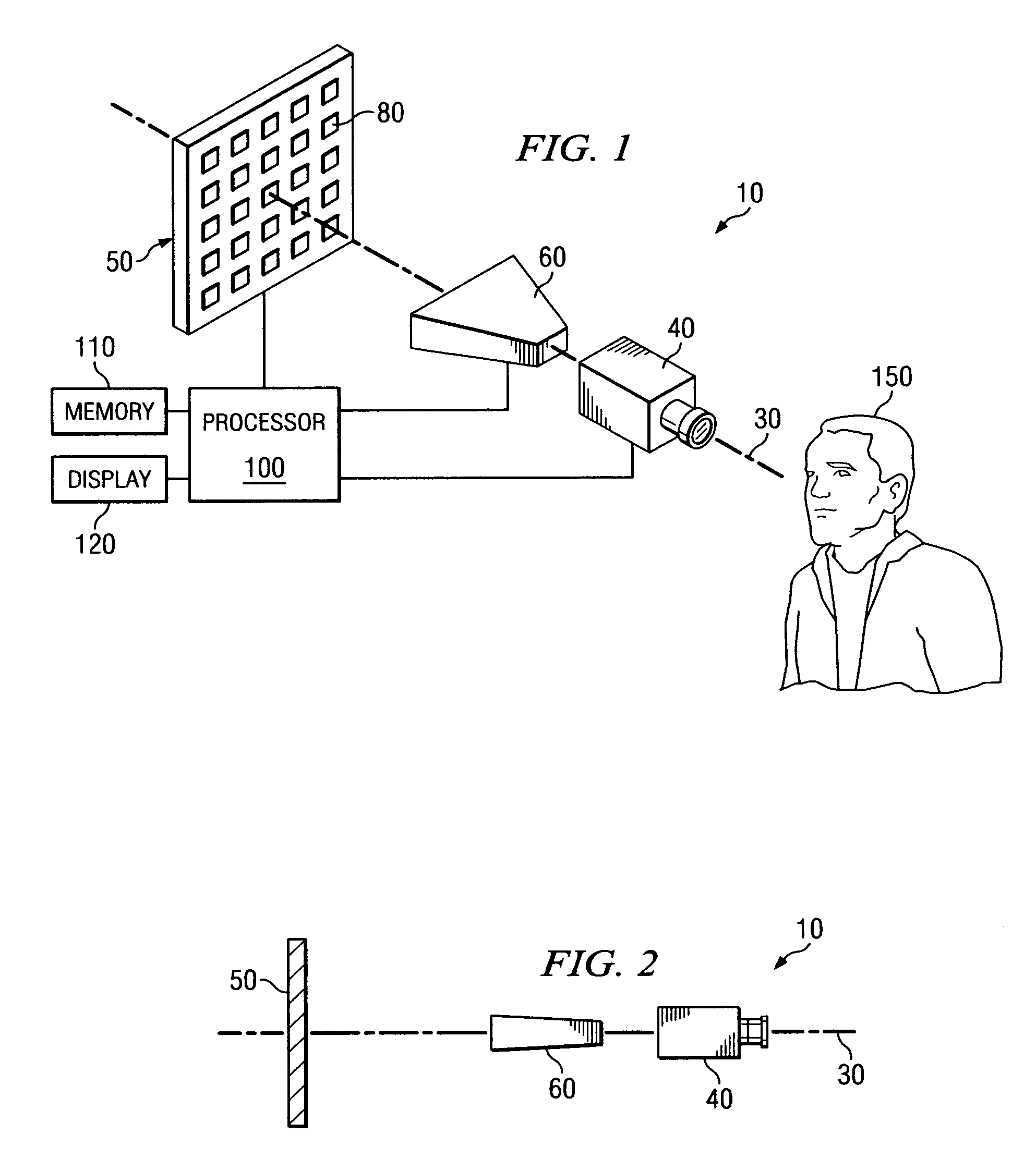
[0029]As used herein, the terms microwave radiation and microwave illumination each refer to the band of electromagnetic radiation having wavelengths between 0.3 mm and 30 cm, corresponding to frequencies of about 1 GHz to about 1,000 GHz. Thus, the terms microwave radiation and microwave illumination each include traditional microwave radiation, as well as what is commonly known as millimeter wave radiation. In addition, as used herein, the term “microwave imaging system” refers to an imaging system operating in the microwave frequency range, and the resulting images obtained by the microwave imaging system are referred to herein as “microwave images.” Furthermore, as used herein, the term “optical imaging system” refers to an imaging system operating in the visible light or near IR frequency range, and the resulting images obtained by the optical imaging system are referred to as “optical images” in order to differentiate these images from microwave images obtained by the microwav...


PUM


Abstract

A coaxial bi-modal imaging system is produced by aligning a microwave transceiver, an optical camera and an antenna array in a coaxial configuration. The microwave transceiver is operable to emit microwave radiation to illuminate an object and to receive reflected microwave radiation reflected from the object to capture a microwave image of the object. The antenna array includes a plurality of antenna elements, each programmable with a respective transmit direction coefficient to direct the microwave radiation emitted from said microwave transceiver toward a target on the object, and each programmable with a respective receive direction coefficient to direct the reflected microwave radiation reflected from said target towards said microwave transceiver. The optical camera is configured to capture an optical image of said object.

Description

CROSS-REFERENCE TO RELATED APPLICATIONS[0001]This application is related by subject matter to U.S. Pat. No. 7,224,314, entitled “A Device for Reflecting Electromagnetic Radiation,” which was filed on Nov. 24, 2004 and issued on May 29, 2007; U.S. patent application Ser. No. 10 / 997,583, entitled “Broadband Binary Phased Antenna,” which was filed on Nov. 24, 2004; and U.S. Pat. No. 6,965,340, entitled “System and Method for Security Inspection Using Microwave Imaging,” which was filed on Nov. 24, 2004 and issued on Nov. 15, 2005.[0002]This application is further related by subject matter to U.S. Pat. No. 7,283,085, entitled “System and Method for Efficient, High-Resolution Microwave Imaging Using Complementary Transmit and Receive Beam Patterns,” which was filed on Mar. 24, 2005 and issued on Oct. 16, 2007; U.S. Pat. No. 7,183,963, entitled “System and Method for Inspecting Transportable Items Using Microwave Imaging,” which was filed on Mar. 24, 2005 and issued on Feb. 27, 2007; U.S....

Claims


Application Information

Patent Timeline
Patent Type & Authority Patents(United States)
IPC IPC(8): G01S13/89G01S13/86G01S13/00
CPCG01S7/4026G01S13/89G01S13/867G01S2013/0254
Inventor YOUNG, JAMES E.LEE, GREGORY S.WEEMS, WILLIAM
Owner AGILENT TECH INC
Why Eureka
Try Eureka