Polarization-diverse antenna array and associated methods

a technology of antenna array and polarization, applied in the field of communication, can solve the problems of increasing physical load, increasing the cost of multiple antennas, and limited antenna platform space, and achieve the effect of quick deploymen

Inactive Publication Date: 2009-03-17
HARRIS CORP
View PDF17 Cites 27 Cited by
  • Summary
  • Abstract
  • Description
  • Claims
  • Application Information

AI Technical Summary

Benefits of technology

[0022]The antenna is small, lightweight and inexpensive. The antenna may be quickly deployable without the need to adjust the position, and it may be able to be attached or placed on any material. Such an antenna is preferably three-dimensionally omnidirectional, and may support multipath mitigation such as diversity reception, and / or multiple-input, multiple-output (MIMO). Deployment of the antenna and / or node may be by attachment (e.g. sticking it on a wall or post) or by tossing (throwing, rolling, or setting it down). No manual positioning is necessary by the user.

Problems solved by technology

Unfortunately, providing multiple antennas is costly and increases the physical load.
Furthermore, antenna platform space is typically limited and spatial diversity increases the size.
If these conventional antennas provide multipath mitigation such as diversity reception, and / or multiple-input, multiple-output (MIMO), then they typically: may not be compact and ruggedized; may require some positioning and / or adjustment; may not be three-dimensionally omnidirectional; and may not be useable near or attachable to some surfaces.

Method used


Image

  • Polarization-diverse antenna array and associated methods
  • Polarization-diverse antenna array and associated methods
  • Polarization-diverse antenna array and associated methods

Examples


Embodiment Construction

[0029]The present invention will now be described more fully hereinafter with reference to the accompanying drawings, in which preferred embodiments of the invention are shown. This invention may, however, be embodied in many different forms and should not be construed as limited to the embodiments set forth herein. Rather, these embodiments are provided so that this disclosure will be thorough and complete, and will fully convey the scope of the invention to those skilled in the art. Like numbers refer to like elements throughout, and prime notation is used to indicate similar elements in alternative embodiments.

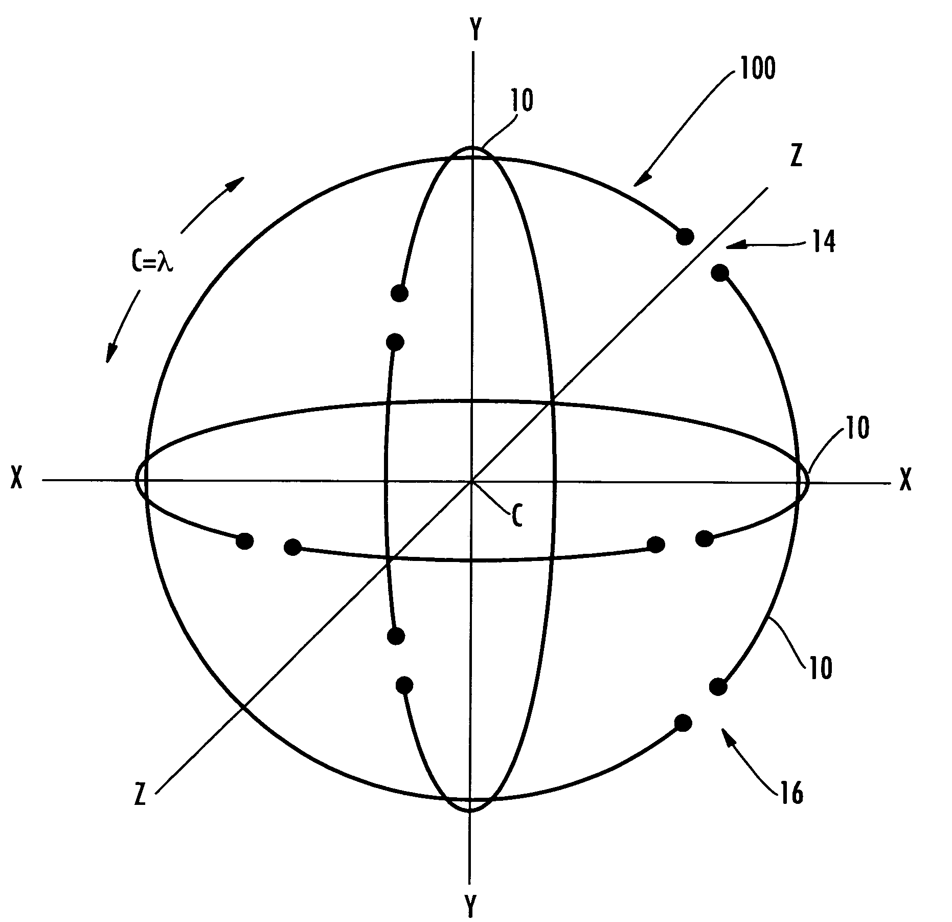
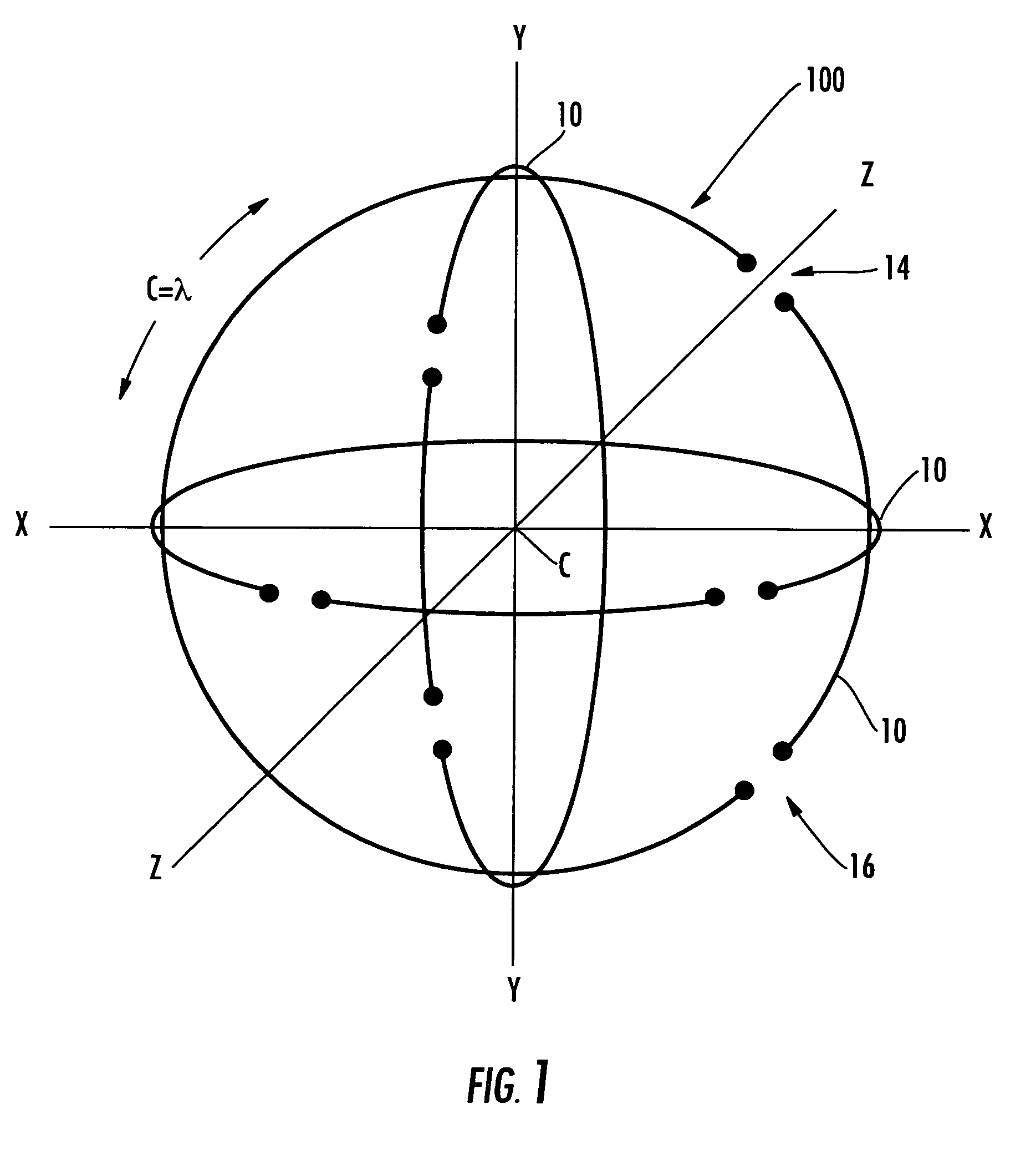
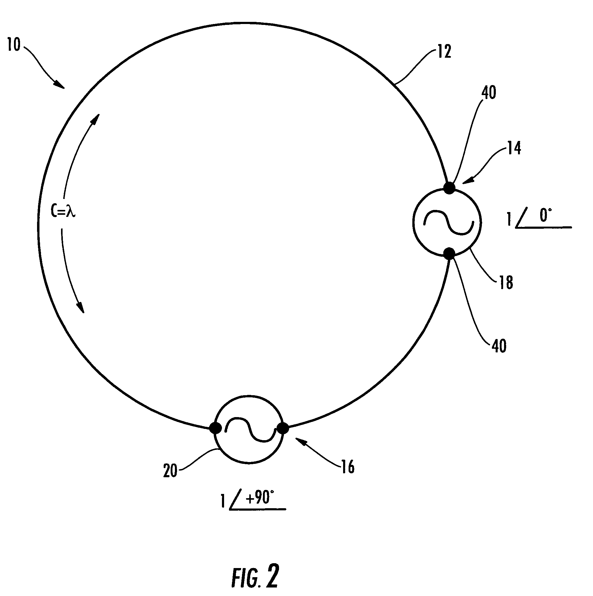
[0030]Referring initially to FIGS. 1-3, a compact antenna array 100 that includes polarization diversity and is three-dimensionally omnidirectional will now be described. The polarization-diverse antenna array 100 includes three orthogonal loop antennas 10 having a common center C and lying on a common spherical surface. Each loop antenna 10 comprises a loop electrical cond...


PUM

PropertyMeasurementUnit
resistanceaaaaaaaaaa
lengthaaaaaaaaaa
electrical conductoraaaaaaaaaa

Abstract

The polarization-diverse antenna array includes three orthogonal loop antennas having a common center, e.g. together defining a sphere. Each loop antenna includes a loop electrical conductor. Two signal feedpoints are along the loop electrical conductor and separated by a fraction of a length of the loop electrical conductor. Each of the signal feedpoints includes a series signal feedpoint so that a polarization diversity controller coupled thereto may selectively provide vertical, horizontal, lefthand circular and righthand circular polarization for a single loop electrical conductor, including simultaneous (dual) polarizations. These signal feedpoints may supply signals with vertical, horizontal, lefthand circular and righthand circular polarization from each of the three orthogonal look-angles provided by the three loop electrical conductors. Thus the antenna array may provide a compact facility for using Diversity Combining to improve communications performance and / or Multiple-Input, Multiple-Output (MIMO) schemes that furthermore also increase capacity. The polarization-diverse antenna array provides a rigorous polarization and look angle approach for communications diversity.

Description

GOVERNMENT LICENSE RIGHTS[0001]This invention was made was made with Government support under Contract No. NBCH-C-05-0056 awarded by the United States Department of Defense. The Government has certain rights in this invention.FIELD OF THE INVENTION[0002]The present invention relates to the field of communications, and, more particularly, to antennas for wireless communications and related methods.BACKGROUND OF THE INVENTION[0003]For background, an antenna is a transducer that converts radio frequency electric current to electromagnetic waves that are radiated into space. The antenna may also convert electromagnetic waves into electric current. The electric field or “E” plane determines the polarization or orientation of the radio wave. Most antennas operate using either linear or circular polarization.[0004]A linearly polarized antenna radiates in one plane. In a circularly polarized antenna, the plane of polarization rotates in a circle making one complete revolution during one per...

Claims


Application Information

Patent Timeline
Patent Type & Authority Patents(United States)
IPC IPC(8): H01Q7/00
CPCH01Q7/00H01Q21/24Y10T29/49016
Inventor PARSCHE, FRANCIS EUGENETEBBE, DENNIS LEE
Owner HARRIS CORP
Why Eureka
Try Eureka