Method and interface elements for finite-element fracture analysis

a finite element and fracture analysis technology, applied in the field offinite element structural analysis methods, can solve the problems of inability to predict the initiation or propagation of cracks in materials using existing finite element computer modeling techniques, hampered prediction of crack initiation and propagation, and limitations of techniques

Active Publication Date: 2009-03-17
THE BOEING CO
View PDF26 Cites 22 Cited by
  • Summary
  • Abstract
  • Description
  • Claims
  • Application Information

AI Technical Summary

Benefits of technology

[0032]FIG. 5 shows a higher-order interface element

Problems solved by technology

The prediction of crack initiation and propagation in a material using existing finite element computer modeling techniques has been hampered by a number of limitations of the techniques.
The existing techniques cannot easily predict the initiation or propagation of cracks in structures containing material or geometric non-linearities or exhibiting non-linear material or geometric response (e.g., as a result of large displacements), cannot easily predict the propagation of multiple crack tips on one-dimensional cracks (either two tips on a single crack, or multiple cracks), and cannot easily handle finite area cracks involving crack fronts.
The technique requires tedious post-processing of multiple finite element solutions.
Additionally, if non-linearities exist in the model, difficulties arise

Method used


Image

  • Method and interface elements for finite-element fracture analysis
  • Method and interface elements for finite-element fracture analysis
  • Method and interface elements for finite-element fracture analysis

Examples


Embodiment Construction

[0036]The present invention now will be described more fully hereinafter with reference to the accompanying drawings, in which preferred embodiments of the invention are shown. This invention may, however, be embodied in many different forms and should not be construed as limited to the embodiments set forth herein; rather, these embodiments are provided so that this disclosure will be thorough and complete, and will fully convey the scope of the invention to those skilled in the art. Like numbers refer to like elements throughout.

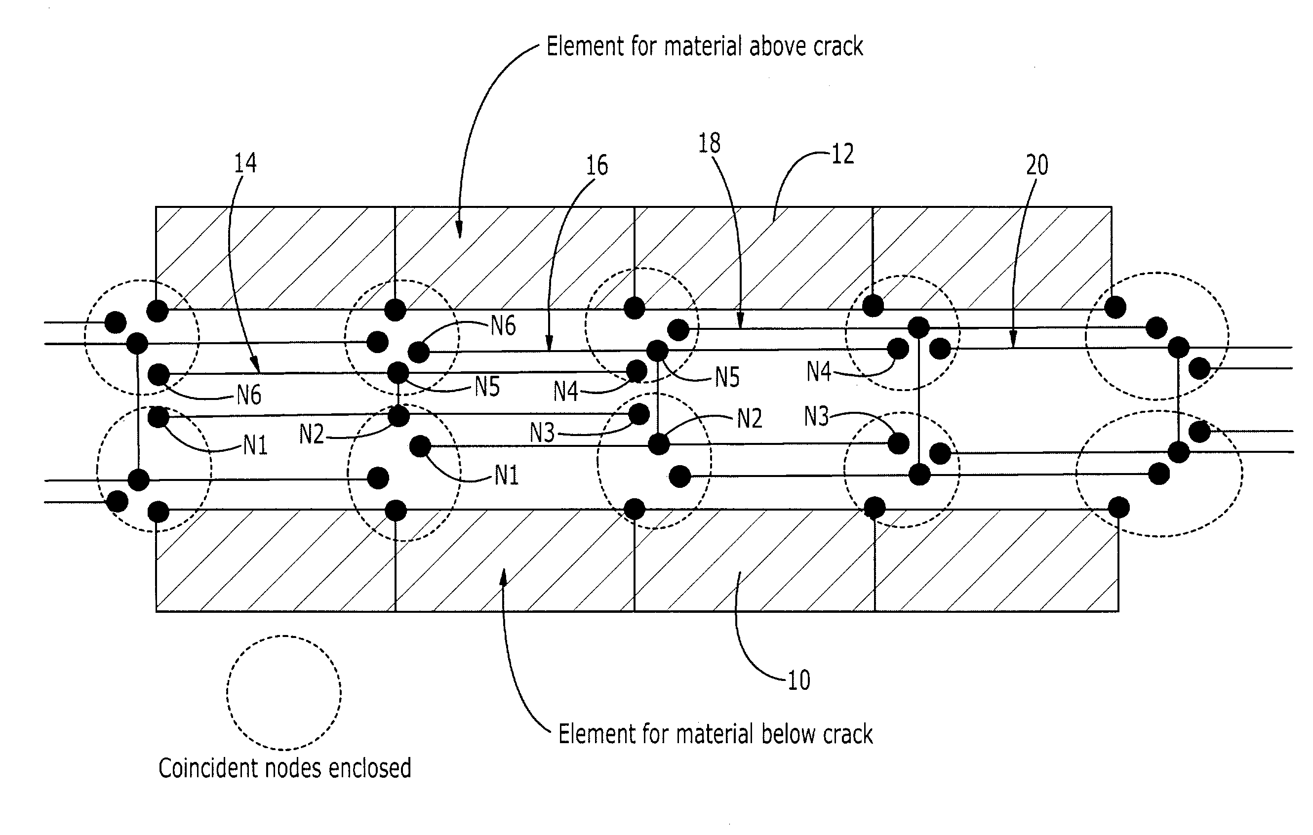
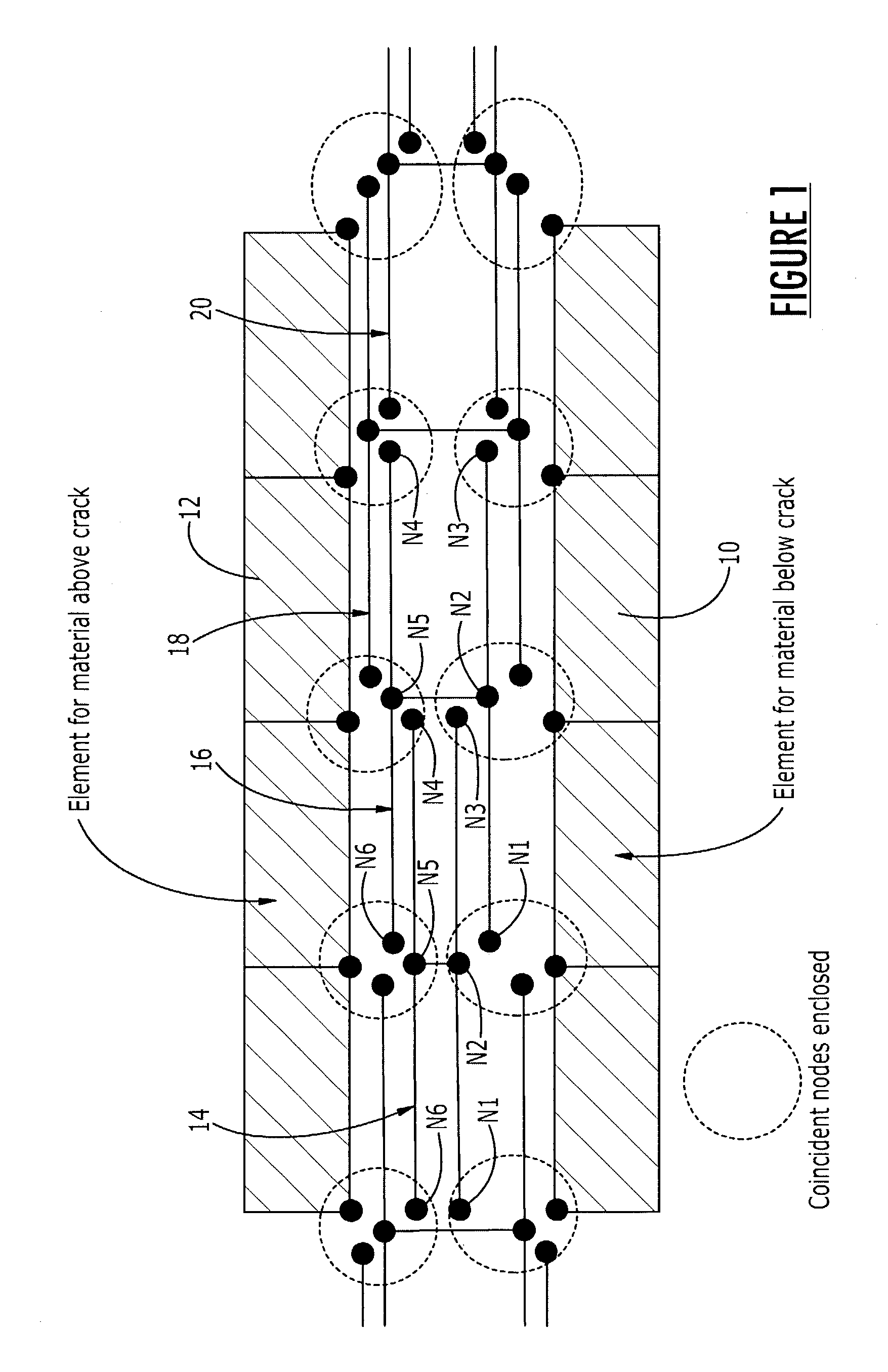
[0037]The invention relates to a method for predicting the behavior of a crack in a structure (e.g., a composite member, a metal member, etc.) subjected to external loading that may cause the crack to grow in length, such growth being referred to herein as “propagation” of the crack. The method of the invention is advantageously implemented within a finite element model (FEM) on a computer. Finite element modeling of structures is widely used for determini...


PUM


Abstract

A finite element method for predicting crack opening and propagation entails defining a succession of overlapping interface elements at a potential crack plane, each element having a bound node pair and side node pairs spaced from the bound node pair to sense approach of a crack. An energy-based fracture mechanics criterion determines whether release occurs at the bound nodes and, if so, the displacement between the bound nodes is calculated based on a strain softening law. The process is repeated for each element in sequence.

Description

FEDERALLY SPONSORED RESEARCH AND DEVELOPMENT[0001]This invention was made with Government support under Contract F33615-98-3-5103 awarded by the Department of the Air Force. The Government has certain rights in this invention.FIELD OF THE INVENTION[0002]The present invention relates to finite element structural analysis methods, and more particularly to methods for analyzing crack initiation and propagation in a material using finite element computer modeling.BACKGROUND OF THE INVENTION[0003]The prediction of crack initiation and propagation in a material using existing finite element computer modeling techniques has been hampered by a number of limitations of the techniques. The existing techniques cannot easily predict the initiation or propagation of cracks in structures containing material or geometric non-linearities or exhibiting non-linear material or geometric response (e.g., as a result of large displacements), cannot easily predict the propagation of multiple crack tips on...

Claims


Application Information

Patent Timeline
IPC IPC(8): G06F9/455G06F17/50
CPCG06F17/5018Y10T428/249953Y10T428/31504G06F30/23
Inventor DEOBALD, LYLE R.DOPKER, BERNHARDMABSON, GERALD E.
Owner THE BOEING CO
Why Eureka
Try Eureka