
Munitions energy system

a technology of energy system and munitions, applied in the field of energy system for powering munitions, can solve the problems of existing munition energy system, low reliability, and power consumption before, during and after the launch of munitions, and achieve the effect of greater manufacturability and reliability, and low cos

Inactive Publication Date: 2009-03-24
UNITED STATES OF AMERICA THE AS REPRESENTED BY THE SEC OF THE ARMY
View PDF5 Cites 64 Cited by
  • Summary
  • Abstract
  • Description
  • Claims
  • Application Information

AI Technical Summary

Benefits of technology

[0012]The munitions energy system of the present invention also meets the strict requirements imposed by munitions applications, including: survivability in the face of extreme accelerations and temperatures; long shelf-life (e.g., 20 years); and limited available volume. Furthermore, the system of the present invention can be implemented at lower cost and with greater manufacturability and reliability than conventional systems.

Problems solved by technology

Furthermore, for some munitions, power consumption takes place before, during and after the launch of the munition.
Existing munition energy systems suffer from several problems, including low reliability, limited shelf life, poor gun launch survivability, and high cost.
Common causes of low reliability are the need for multiple batteries and their construction.
A disadvantage of such systems is primarily the time needed to mix the reactive components and bring the battery output voltage to the desired level.
Lithium battery technologies, however, are prone to leakage and have much lower shelf lives when compared to thermal or liquid reserve batteries.
The second battery system which is added to provide power during the early portions of the launch thus severely degrades the performance of the munition energy system, its shelf life and survivability.
In addition to shelf-life, reliability and survivability, the powering of gun-fired munitions presents additional challenges including, for example, the ability to be stored and operate over wide temperature ranges; acceleration forces ranging from ten to one hundred thousand times the weight of the system; and strict limitations on the volume of space available for housing the energy system.
The problem with such battery technologies is that these have much lower shelf lives, limited temperature performance and perform poorly in high “G” environments.
Older battery technologies often require multiple batteries, have poor shelf life and temperature performance, are large, occupying precious munition volume, have poor acceleration performance, are expensive to produce, and are unreliable.
In addition, such munitions are commonly subjected to high levels of vibration during transportation and loading.
Therefore, even more space is required for the housing and protection of the energy systems of gun-fired munitions.
As a result, a considerable portion of the available space must be assigned to house the batteries and their related components.
In addition to the aforementioned problems, conventional energy systems for munitions also face problems related to deterioration during long periods of storage (e.g., twenty years), and the high cost of production and assembly of the projectile and the related hardening efforts and testing, among others.

Method used


Image

  • Munitions energy system
  • Munitions energy system
  • Munitions energy system

Examples


Embodiment Construction

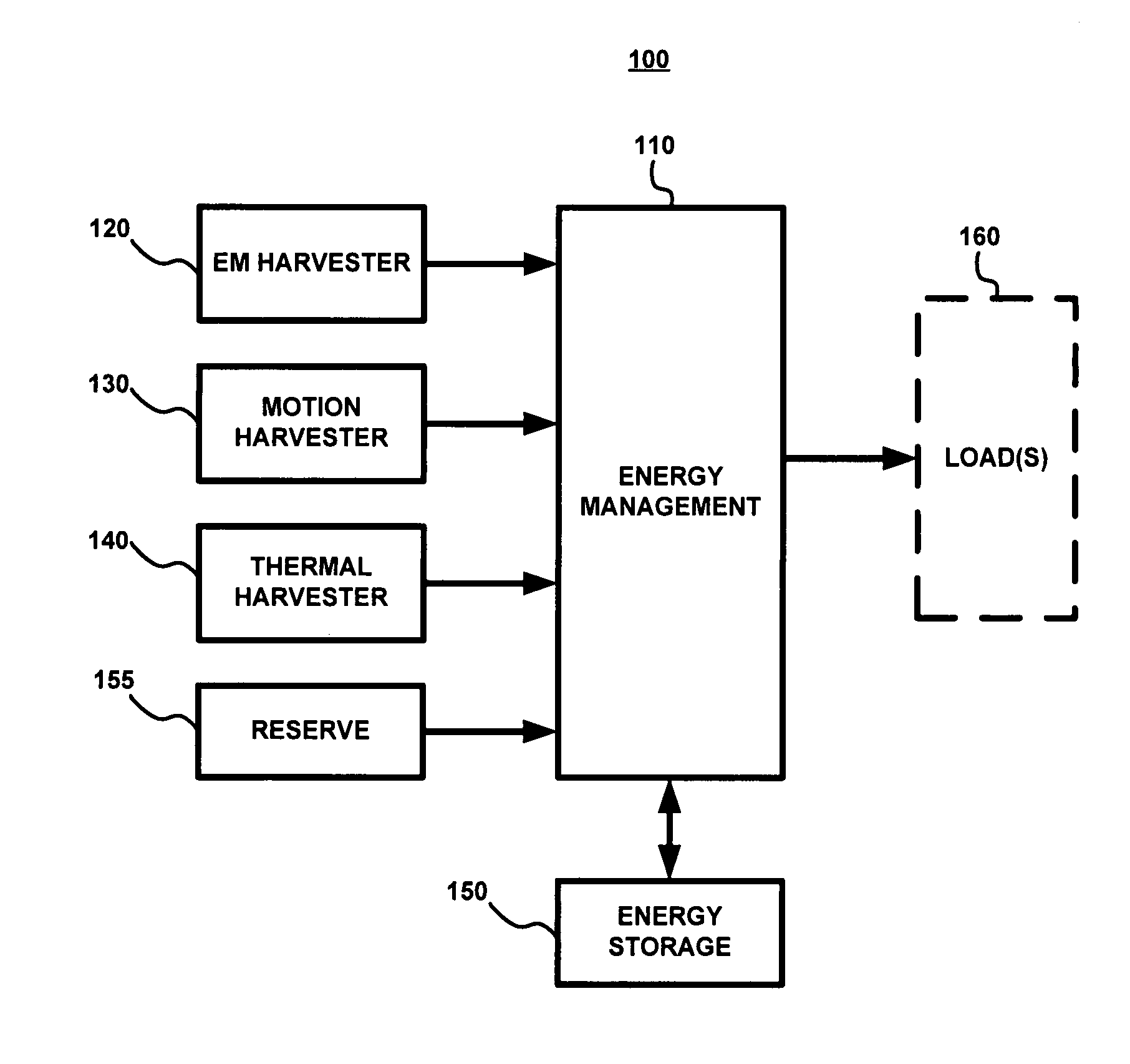
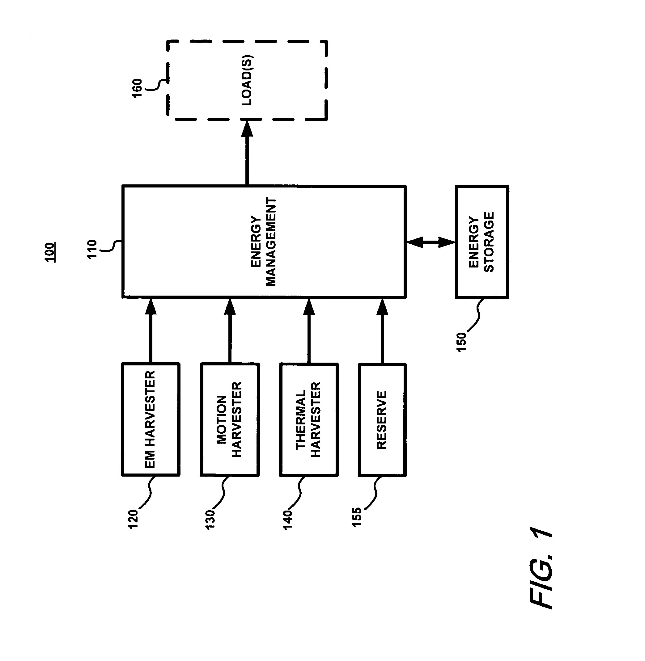
[0024]FIG. 1 shows a block diagram of an exemplary embodiment of a munitions energy system 100 in accordance with the present invention. The exemplary system 100 includes an energy management unit 110 which interacts with one or more energy harvesting devices, including, for example, an electromagnetic (EM) harvester 120, a motion harvester 130, and a thermal harvester 140. The energy harvesting devices harvest energy from the environment of the munition and may include other devices not listed herein. Exemplary energy harvesting device are described in greater detail below. The system 100 also includes an energy storage device 150 which can provide as well as receive energy. The energy storage device 150 may include, for example, one or more rechargeable batteries, capacitors, or the like. As will be understood, the specific implementation of the storage device 150 will depend on the application. In an exemplary embodiment, the energy storage device 150 can be implemented using a s...


PUM


Abstract

A munitions energy system combines various sources of energy generation with energy storage to provide power to a munition through various stages of the munition's operation. The system uses energy harvesting technologies which convert energy captured from the environment of the munition to electrical power which can be used to meet the munition's power needs. Energy can be harvested from the mechanical, thermal, and electromagnetic environment of the munition. The harvested energy can be stored by the system for later use. The system can also receive energy from conventional sources such as batteries and manage the energy from all sources to meet the power requirements of the munition.

Description

CROSS-REFERENCE TO RELATED APPLICATIONS[0001]The present application claims priority from U.S. Provisional Patent Application No. 60 / 595,775, which was filed Aug. 4, 2005 and which is incorporated herein by reference in its entirety.FIELD OF THE INVENTION[0002]The present invention relates generally to energy systems and, in particular, it relates to energy systems for powering munitions.BACKGROUND OF THE INVENTION[0003]Current and future munitions energy systems need to be able to provide power for munitions having an ever increasing number of sensors, actuators, and communications requirements. Furthermore, for some munitions, power consumption takes place before, during and after the launch of the munition.[0004]Existing munition energy systems suffer from several problems, including low reliability, limited shelf life, poor gun launch survivability, and high cost. Common causes of low reliability are the need for multiple batteries and their construction. For long shelf life and...

Claims


Application Information

Patent Timeline
Patent Type & Authority Patents(United States)
IPC IPC(8): F42B99/00H02N3/00H02N6/00
CPCF42C11/008H02S10/30H02J3/32F42C11/02Y02E10/50
Inventor PEREIRA, CARLOS M.JANOW, CHRISMCMULLAN, CHARLES WILLIAM
Owner UNITED STATES OF AMERICA THE AS REPRESENTED BY THE SEC OF THE ARMY
Learn More