
Multi-size tire filling apparatus and method

a tire filling and tire technology, applied in the field of tire filling stations, can solve the problems of increasing quality demands that cannot always be satisfied, and the accuracy of the resulting tire inflation pressure is impaired, and achieves the effects of good tire inflation pressure accuracy, good size matching precision, and simple, robust and effective

Inactive Publication Date: 2009-03-24
SCHENCK ROTEC GMBH
View PDF41 Cites 17 Cited by
  • Summary
  • Abstract
  • Description
  • Claims
  • Application Information

AI Technical Summary

Benefits of technology

[0011]In view of the above, it is an object of invention to provide a tire-filling method and apparatus with simple measures to achieve a high inflation or filling accuracy as well as a good reproducibility of the achieved inflation pressure in wheel-tire combinations of different sizes or dimensions. It is another object of the invention to be able to service the greatest possible number of different sizes or dimensions of wheel-tire combinations with a single tire filling station. Still another object of the invention is to provide an increased precision of matching the size of the tire filling bell or ring to the particular size of the wheel-tire combination that is to be filled. The invention further aims to avoid or overcome the disadvantages of the prior art, and to achieve additional advantages, as apparent from the present specification. The attainment of these objects is, however, not a required limitation of the claimed invention.
[0019]The invention is generally based on the recognition that the size difference or spacing distance between the outer diameter of a wheel rim and the inner diameter of a filling bell used to fill the tire mounted on this wheel rim is the critical value or parameter determining the resulting accuracy of the tire inflation pressure achieved in the finally inflated tire. Namely, the smaller that this size difference or spacing gap is, the better will be the accuracy of the tire inflation pressure. This particularly means that the achieved air pressure can be more accurately reproduced from one tire to the next, and that a particular desired or target air pressure can be more accurately achieved for each given tire.
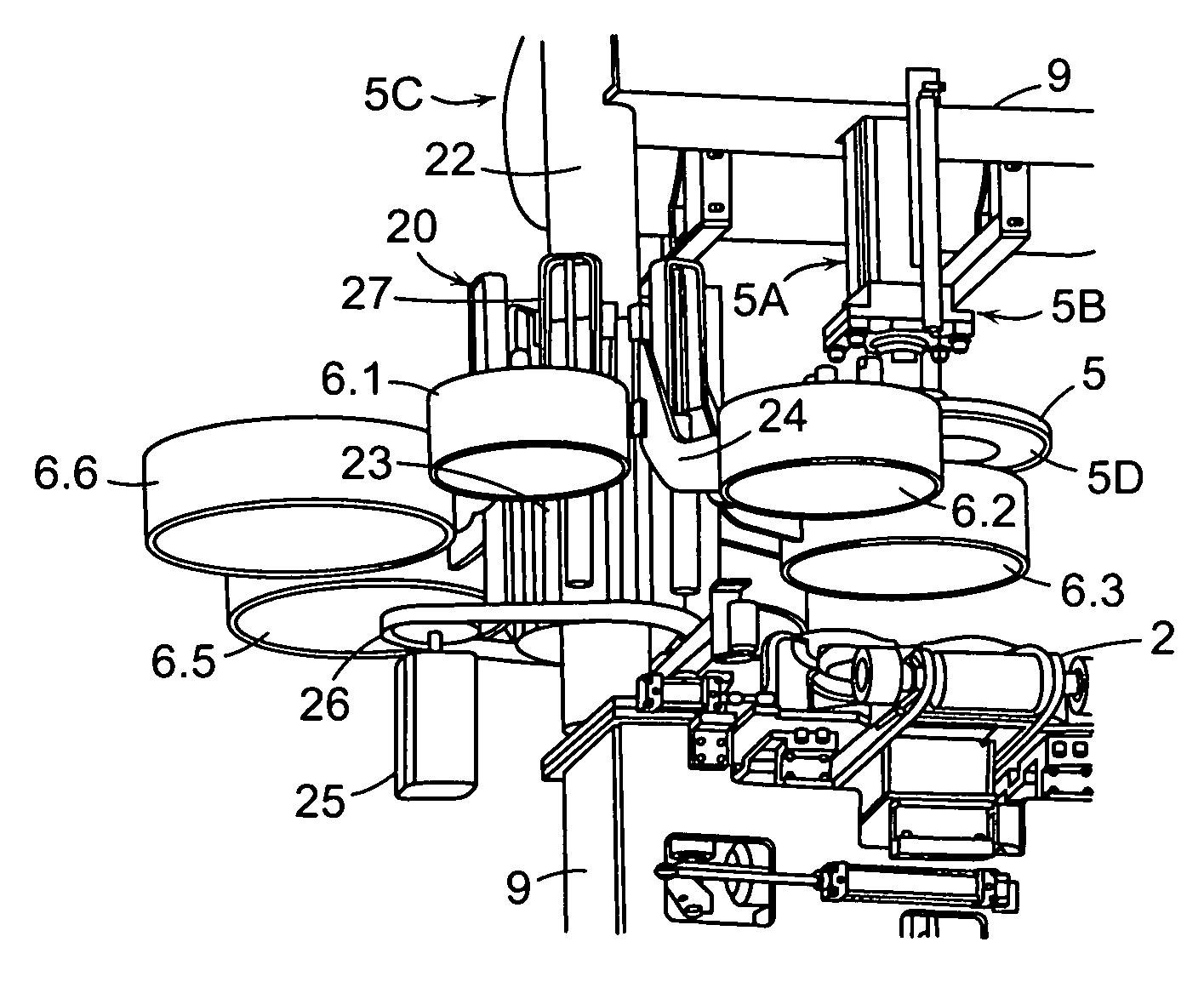
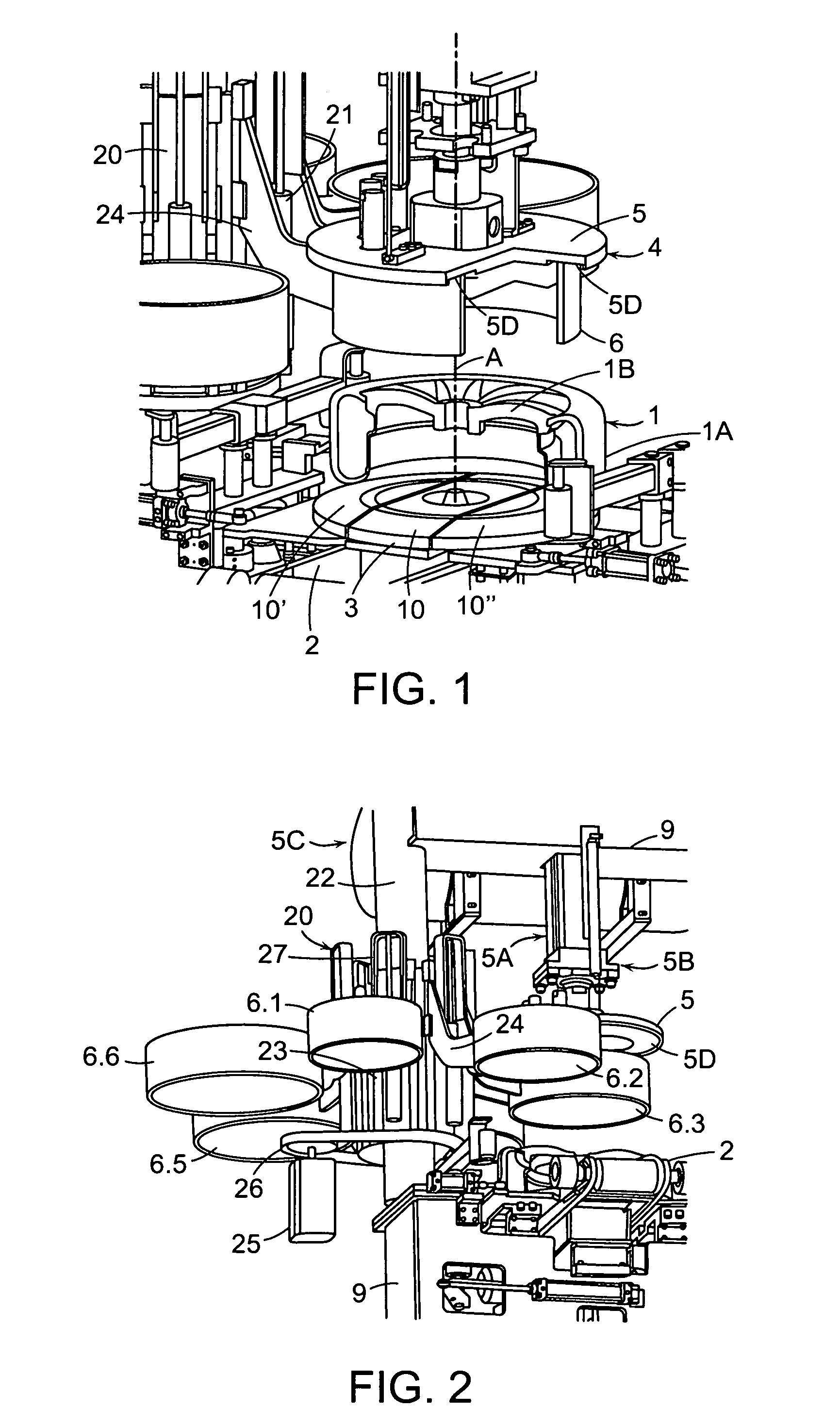
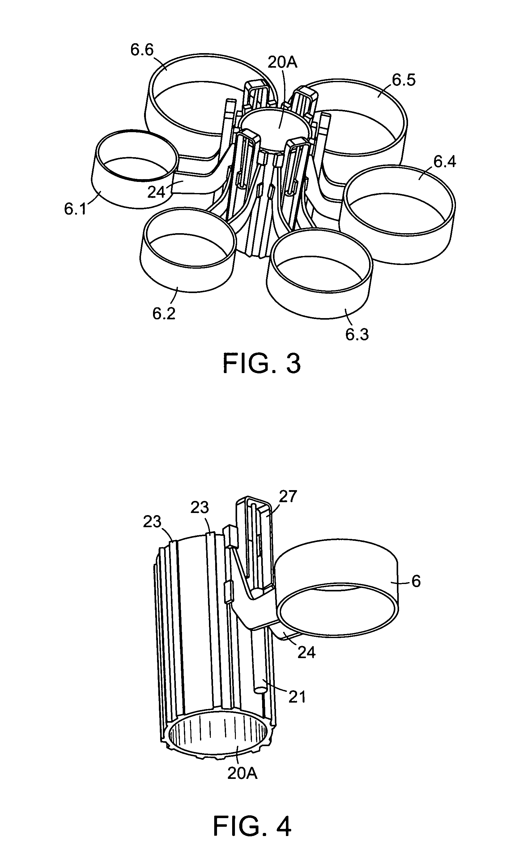
[0023]By providing a relatively great number of differently-sized filling rings, e.g. preferably six different filling rings, in a single tire filling station according to the invention, this provides a good size matching precision, i.e. the ability to closely match the size of the selected filling ring to the size of the wheel-tire combination that is to be filled. It has been unexpectedly and surprisingly found that a very good tire inflation pressure accuracy can already be achieved if one filling bell or filling ring with a certain opening diameter is used for filling wheel-tire combinations having either of two successive wheel rim sizes. In other words, each filling ring can be used to fill two different successive wheel-tire sizes. Thus, the preferred set of six filling rings having different diameters can be used to service a total of twelve different wheel-tire sizes, which covers a standard wheel rim size range from 13 inches to 24 inches, i.e. including twelve successive standard wheel rim sizes that each differ successively by one inch. In this regard, the successive diameters of the tire filling rings differ by two inches from one another, and each will be used to service the next larger and the next smaller wheel rim size. Thereby, the invention makes it possible to fill wheel-tire combinations covering the entire wheel size spectrum of wheels available in the ordinary market for automobiles, using a single tire filling station and achieving the required accuracy and reproducibility of the filled tire air pressure.
[0024]The arrangement of the several filling rings along a circular line or path about the hub of a carousel rotation arrangement is an extremely simple, robust and effective embodiment for selecting and moving any required individual one of the filling rings into the operating position to cooperate with the single filling plate. This arrangement is especially simple if the hub of the carousel arrangement is rotatably arranged on an existing column of the apparatus that is necessarily provided to connect together the upper part and the lower part of the machine frame thereof.
[0025]The arrangement of the filling rings on a linear motion arrangement makes it possible to effectively utilize the available space above the linear transport path of the wheel-tire combinations in an especially space-saving manner. This results in an overall compact construction of the tire filling station.

Problems solved by technology

It has been found in practice, however, that these increasing quality demands cannot always be satisfied if three different successive rim sizes of wheels / tires are to be serviced with a single tire filling bell or ring, because the precision of the size match is not sufficient and the accuracy of the resulting tire inflation pressure is thereby impaired.

Method used


Image

  • Multi-size tire filling apparatus and method
  • Multi-size tire filling apparatus and method
  • Multi-size tire filling apparatus and method

Examples


first embodiment

[0047]Most basically, the tire filling bell 4 is embodied and constructed in a multi-part manner according to the present invention, and is essentially formed of a combination of an air feed and pressing member (e.g. embodied as a tire filling plate 5) and a filling chamber member (e.g. embodied as a tire filling ring 6). In a first embodiment, the tire filling ring 6 is essentially simply an annular cylindrical shell or pipe section. The tire filling ring 6 may be any respectively selected one tire filling ring among an available plurality of differently-sized ones of such tire filling rings 6.1, 6.2, 6.3, 6.4, 6.5, and 6.6. The filling plate 5 and the filling ring 6 may respectively be constructed of steel or some other suitable metal, or any other known or future developed material suitable for the intended purpose. The filling plate 5 and / or the filling ring 6 may be provided with a seal layer or a seal ring, e.g. 5D, on a face of the plate 5 and / or on an end edge or rim of the ...

second embodiment

[0066]In this second embodiment of FIGS. 8 to 11, each filling ring 6′ or filling chamber member includes an annular cylindrical sleeve or ring wall 6A, or a stepped-diameter ring wall 6D, and an at least partially closed top plate or top cap 6B having a first opening 6C therein. The ring wall 6A or 6D has an open bottom end forming a second opening bounded by a bottom edge rim. Thus, each filling ring 6′ in such an embodiment has a configuration of an inverted bowl, or of a bell or dome. An air feed and pressing member 5′, like a smaller-diameter filling plate 5, makes sealing contact on a seal ring 6E around the first opening 6C in the top cap 6B of the filling ring 6′.

[0067]While the bottom second openings of the several filling rings 6′ have respective different diameters, the top first openings 6C of the several filling rings 6′ preferably all have the same common diameter, which simplifies the sealed fitting of the air feed and pressing member 5′ thereto. In this regard, the s...


PUM

PropertyMeasurementUnit
diameteraaaaaaaaaa
sizeaaaaaaaaaa
sizeaaaaaaaaaa

Abstract

A tire filling apparatus preferably includes a support and seal arrangement on which a wheel-tire combination is supported in a horizontally lying orientation, a tire filling plate, and a plurality of differently-sized tire filling rings. Based on the diameter of the wheel-tire combination to be filled with air, a properly sized one of the filling rings is selected and positioned coaxially along the wheel axis between the tire and the filling plate. The filling plate moves toward the tire, sealingly contacts the filling ring, and presses the filling ring against the upwardly facing tire sidewall, until an open air filling gap is formed between the tire sidewall bead and the wheel rim. Pressurized air is introduced through the filling plate, the filling ring, and the open air filling gap into the tire interior, until the gap is closed by the increasing air pressure in the tire.

Description

PRIORITY CLAIM[0001]This application is based on and claims the priority under 35 U.S.C. §119 of German Patent Application 10 2004 062 329.5, filed on Dec. 20, 2004, the entire disclosure of which is incorporated herein by reference.FIELD OF THE INVENTION[0002]The invention relates to a tire filling station for filling pressurized air into a pneumatic wheel-tire combination comprising a tire mounted on a wheel rim, such as a mounted motor vehicle tire. The tire filling station is adaptable to different sizes of tires. The invention further relates to a method of filling a tire by filling air through an annular gap between the tire sidewall bead and the wheel rim, whereby the method is also adaptable to different sizes of tires.BACKGROUND INFORMATION[0003]In the high volume series production of motor vehicles on an assembly line, air-filled mounted tires or wheel-tire combinations comprising a tire mounted on a wheel rim, are prepared in a tire mounting production line and are then t...

Claims


Application Information

Patent Timeline
Patent Type & Authority Patents(United States)
IPC IPC(8): B65B31/00
CPCB60C25/05B60C25/132B60C25/145
Inventor PEINELT, ANDREASROGALLA, MARTINLEHR, WERNERLEHMANN, ROLAND
Owner SCHENCK ROTEC GMBH
Learn More