
Method of producing downhole drill bits with integral carbide studs

a technology of carbide studs and drill bits, which is applied in the field of producing/manufacturing earth boring bits with integral carbide studs, can solve the problems of significant resources and time, loss of studs, and the step of requiring the bit to be machined prior to the attachment of the studs, etc., and achieves the effect of easy manufacturing and economics

Inactive Publication Date: 2009-03-24
APPLIED PROCESS
View PDF17 Cites 4 Cited by
  • Summary
  • Abstract
  • Description
  • Claims
  • Application Information

AI Technical Summary

Benefits of technology

"The present invention provides a downhole drill bit for earth boring that uses a plurality of hardened carbide studs in the drill bit head. These carbide studs can be easily and economically manufactured using a lost-foam casting process. The carbide studs are plated in copper or some other suitable material to prevent degradation during the heat treatment process. The carbide studs are securely attached to the drill bit head without requiring subsequent machining, resulting in a more durable and efficient drilling head and bits. The invention also includes a method for manufacturing the downhole drill bit with hardened carbide studs."

Problems solved by technology

Conventionally, these studs are mounted in their seats upon the head of the drill bit by brazing or cementing them to the drill bit, which is economically inefficient, time consuming, and often results in the loss of studs during vigorous drilling.
Furthermore, it is often necessary for the bits to be heavily machined after casting or forging prior to the attachment thereto of any carbide studs, requiring additional labor and costs.
This additional step of requiring the bit to be machined prior to the attachment of the studs requires significant amounts of resources and time.
This extra machining significantly increases production time and cost to the drill bit.
The addition of the sleeves increases production costs as well as the possibility of the incidental release of the studded insert due to the vibrations caused by the earth drilling process.

Method used


Image

  • Method of producing downhole drill bits with integral carbide studs
  • Method of producing downhole drill bits with integral carbide studs
  • Method of producing downhole drill bits with integral carbide studs

Examples


Embodiment Construction

[0028]The following description of the preferred embodiment(s) is merely exemplary in nature and is in no way intended to limit the invention, its application, or uses.

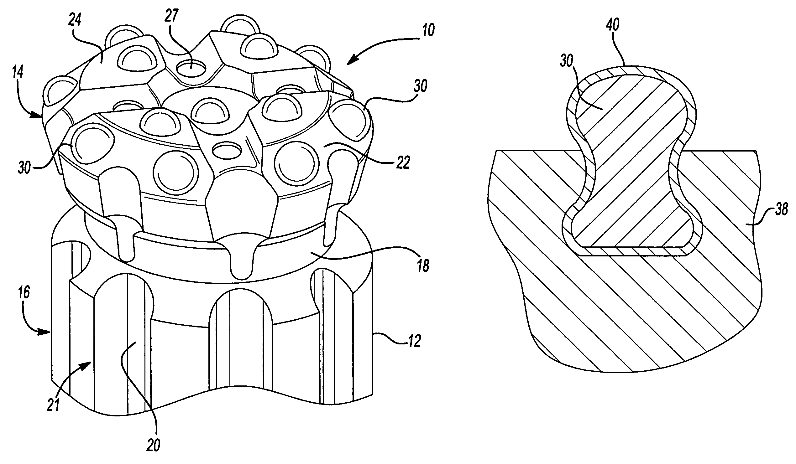
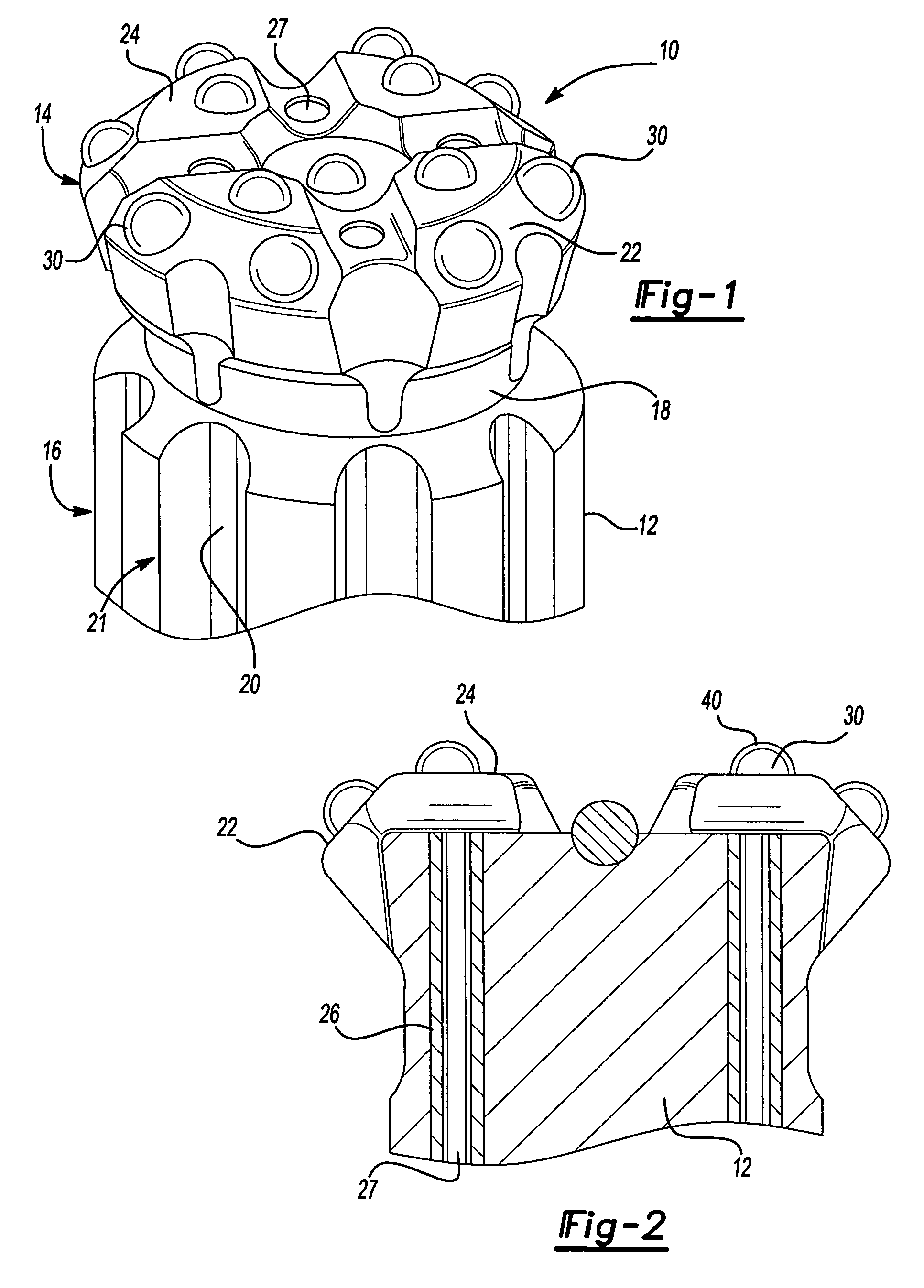
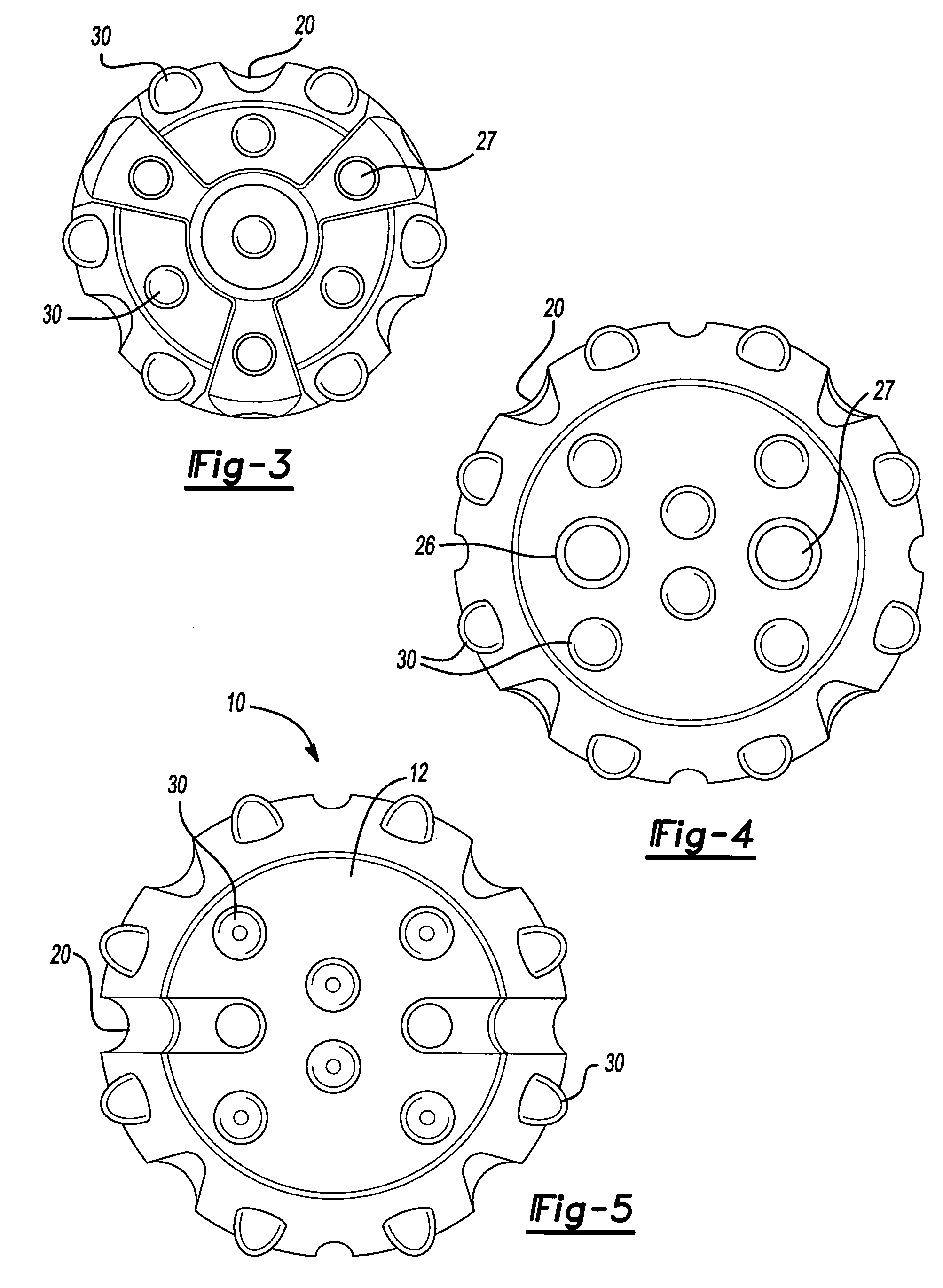
[0029]Referring to the drawings by numeral, and more specifically to FIG. 1, the preferred embodiment of the present invention is shown generally numbered as 10. This drill bit comprises a generally cylindrically shaped cast iron body 12 for attaching to a down hole drilling apparatus of a conventional drill string. The body 12 is formed of cast iron or any suitable alloy, especially a high temperature alloy which will provide for greater strength and endurance. The bit body 12 has an upper grinding portion 14 and a lower shaft portion 16 which subsequently attaches to a drilling apparatus by conventional means.

[0030]Both the upper portion 14 and the lower portion 16 are separated by an annular groove 18, have a plurality of longitudinal recesses 20 within the surface of the bit, created by the mold within which the b...


PUM

PropertyMeasurementUnit
sizeaaaaaaaaaa
shapeaaaaaaaaaa
volumeaaaaaaaaaa

Abstract

A down hole rock drill bit and method of manufacture of the same comprising a cast metal drill bit body having a plurality of hardened carbide studs partially cast in the drill bit body. The drill bit is cast by means of a foam pattern replicating the drill bit, typically made from polystyrene within which a plurality of carbide studs are partially inserted into the grinding surface of the foam drill bit model. The model is then subsequently supported within a vessel of sand and molten metal is poured over the foam, vaporizing it and taking the exact form of the foam pattern and permanently retaining the carbide studs within the metal drill bit.

Description

CROSS-REFERENCE TO RELATED APPLICATIONS[0001]This application is a continuation of U.S. patent application Ser. No. 10 / 229,192 filed on Aug. 27, 2002. The disclosures of the above application is incorporated herein by reference.FIELD OF THE INVENTION[0002]present invention relates to earth boring drill bits. Specifically, this invention relates to a method of producing / manufacturing earth boring bits with integral carbide studs for downhole drilling through rock and other material.BACKGROUND OF THE INVENTION[0003]Rotary drill bits used in earth drilling are generally comprised of a cast, forged or machined material of significant hardness, to keep wear to the drill bit head to a minimum. To further enhance the effect of the drill, drill bit heads often utilize a plurality of hardened studs of tungsten carbide or other hard material mounted in a configuration on the head of the drill bit to increase the durability and efficiency of the bit. Conventionally, these studs are mounted in ...

Claims


Application Information

Patent Timeline
Patent Type & Authority Patents(United States)
IPC IPC(8): E21B10/36B22D19/06E21B10/42E21B10/43E21B10/56
CPCB22D19/06E21B10/43E21B10/56
Inventor BRANDENBERG, KRISTIN RKEOUGH, JOHN RHAYRYNEN, KATHY LWURTSMITH, GERALD J
Owner APPLIED PROCESS
Learn More