Frequency synthesizer

a frequency synthesizer and frequency technology, applied in the direction of electrical equipment, pulse automatic control, etc., can solve the problems of frequency shift, frequency error becomes greater, and the technique does not prevent the occurrence of a frequency shift in the digital phase comparator, so as to prevent the occurrence of a frequency shi

Active Publication Date: 2009-03-24
NIHON DEMPA KOGYO CO LTD
View PDF9 Cites 13 Cited by
  • Summary
  • Abstract
  • Description
  • Claims
  • Application Information

AI Technical Summary

Benefits of technology

[0021]The present invention has been made in consideration of the aforementioned situation, and it is an object of the invention to provide a frequency synthesizer capable of preventing occurrence of a frequency shift upon occurrence of a change in the level of an input to an A / D converter by preventing a situation where PLL control does not work properly.
[0022]To overcome the problem of the conventional techniques, a frequency synthesizer according to the present invention comprises a voltage controlled oscillator that generates a frequency signal according to an input control voltage; a frequency divider that divides the generated frequency signal; an A / D converter that performs analog-to-digital conversion of the divided signal; a phase comparator that compares a phase of the A / D-converted signal with a phase of a reference signal to detect a phase difference, and outputs a phase difference signal according to the phase difference; a D / A converter that performs digital-to-analog conversion of the phase difference signal; and a loop filter that cancels a high-frequency noise, wherein the phase comparator includes, as an automatic gain control circuit, a multiplier provided at a subsequent stage of the A / D converter and an amplitude information detector that detects amplitude information for controlling a gain of the multiplier, and unlock detection means that monitors a value of the amplitude information and detects an unlock state when the value falls within a specific range. The frequency synthesizer makes it possible to prevent a frequency shift from occurring.
[0023]According to the present invention, the phase comparator includes a carrier remove that performs quadrature detection of an output from the A / D converter to acquire a rotational vector which rotates with a frequency difference between an output signal from the A / D converter and a detection signal; an inverse rotational vector multiplier that multiplies a rotational vector by an inverse rotational vector; a phase time difference detector that detects a phase difference every sampling time based on the rotational vector reduced by multiplication; an adder that subtracts a fine adjustment frequency from the detected phase difference; and a phase difference accumulator that accumulates an output from the adder for a given time, and the unlock detection means monitors the value of the amplitude information acquired by the amplitude information detector to which an output from the inverse rotational vector multiplier is branched and input. Unlock detection can be executed according to the value of the phase difference based on the signal subjected to quadrature detection.

Problems solved by technology

When the level of an input to the A / D converter in the conventional frequency synthesizers changes significantly, however, the PLL control in the phase comparator may not work properly, resulting in occurrence of a frequency shift.
It is apparent that there arises a problem such that when the ADC input level varies considerably with respect to the reference value, the frequency error becomes greater.
While the technique of the Patent Document 1 outputs information indicating that a PLL circuit is unlocked before the PLL circuit is actually unlocked, the technique does not prevent a frequency shift in the digital phase comparator from occurring with respect to a change in the level of the input to the A / D converter.
Because the comparison targets are delayed input signals, however, the conventional technique does not prevent a frequency shift with respect to a change in the level of the input to the A / D converter.

Method used


Image

  • Frequency synthesizer
  • Frequency synthesizer
  • Frequency synthesizer

Examples


Embodiment Construction

[0050][Outline of the Invention]

[0051]A preferred embodiment of the present invention will be described below referring to the accompanying drawings.

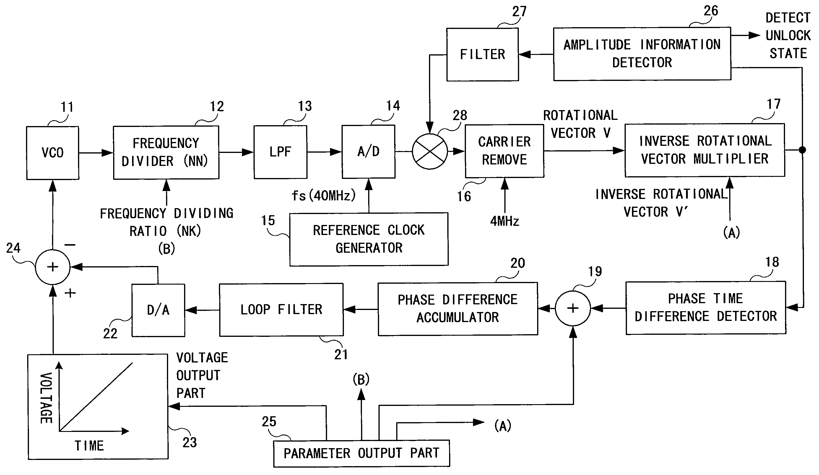
[0052]A frequency synthesizer according to the embodiment of the present invention includes an automatic gain control circuit (AGC) in order to make an output level from an A / D converter constant, and determines an input level to the A / D converter based on an AGC correction value. When the AGC correction value lies within a proper range, it performs a lock (synchronization) process under PLL control in parallel with a gain control at the output of the AD converter with the AGC, and when the value is off the proper range, it detects an unlock state under PLL control thus making it possible to prevent a frequency shift.

[0053][Configuration of Embodiment: FIG. 1]

[0054]The frequency synthesizer according to the embodiment of the present invention will be described referring to FIG. 1. FIG. 1 is a configuration block diagram of the frequency...


PUM


Abstract

Disclosed is a frequency synthesizer capable of preventing occurrence of a frequency shift upon occurrence of a change in the level of an input to an A / D converter by preventing PLL control from being properly operated. The frequency synthesizer includes a carrier remove, an inverse rotational vector multiplier, a phase time difference detector, an adder, a phase difference accumulator, a loop filter, a parameter output part, an amplitude information detector, a filter, and a multiplier configured by an FPGA. Unlock detection means monitors the value of amplitude information detected by the amplitude information detector. When the value lies within a proper range, a lock (synchronization) process is performed under PLL control, whereas when the value is off the proper range, an unlock state in PLL control is detected.

Description

BACKGROUND OF THE INVENTION[0001]1. Field of the Invention[0002]The present invention relates to a frequency synthesizer which provides an oscillation output of a desired frequency, and, more particularly, relates to a frequency synthesizer capable of preventing occurrence of a frequency shift upon occurrence of a change in the level of an input to an A / D (Analog-Digital) converter by preventing a situation where PLL (Phase Locked Loop) control does not work properly.[0003]2. Description of the Related Art[0004]A conventional frequency synthesizer will be described referring to FIG. 2. FIG. 2 is a configuration block diagram of the conventional frequency synthesizer.[0005]As shown in FIG. 2, the conventional frequency synthesizer has a VCO (Voltage Controlled Oscillator) 1, a frequency divider 2, a reference oscillation circuit 3, an A / D converter 4, a phase comparator 5, a digital filter 6, a D / A (Digital / Analogue) converter 7, and an analog filter 8.[0006]The VCO 1 is a voltage co...

Claims


Application Information

Patent Timeline
Patent Type & Authority Patents(United States)
IPC IPC(8): H03L7/085H03L7/095H03L7/18
CPCH03L7/085H03L7/095H03L7/18
Inventor KOBATA, TSUKASA
Owner NIHON DEMPA KOGYO CO LTD
Why Eureka
Try Eureka