Data distribution server and terminal apparatus

a terminal and server technology, applied in the direction of television systems, frequency-division multiplex, broadcast service distribution, etc., can solve the problems of inability to achieve a complete holding of the received state at the terminal unit, and reduced line available efficiency, etc., to achieve stable image streaming

Active Publication Date: 2009-03-24
MAXELL HLDG LTD
View PDF12 Cites 72 Cited by
  • Summary
  • Abstract
  • Description
  • Claims
  • Application Information

AI Technical Summary

Benefits of technology

[0010]The method described in the Patent Document 2 is carried out such that the receiving terminal unit always continues to transmit information concerning the received state relative to the distribution server in order to cause the distribution server to judge the received state at the receiving terminal unit. Due to this fact, the receiving terminal unit must always execute both transmission and reception at the time of an image streaming operation, resulting in the fact that this method produces a problem in that the line available efficiency is reduced, and, at the same time, the processing load at the receiving terminal unit is increased.
[0011]This invention is provided to solve the aforesaid problems, and it is an object of this invention to provide means for causing the receiving terminal itself to accurately monitor the receiving bit rate at the time of an image streaming operation, so as to be capable of executing a stable image streaming by requesting the distribution server to switch the receiving bit rate to the most-suitable image bit rate in response to the result of the monitoring operation.

Problems solved by technology

However, in the case where many receiving terminals are concentrated at a certain one base center and the like, it sometimes happens that the intensity of an electromagnetic wave and the data communication speed are not necessarily proportionate to each other.
Thus, in the case of this method, it is not possible to attain a complete holding of the received state at the terminal unit.
Due to this fact, the receiving terminal unit must always execute both transmission and reception at the time of an image streaming operation, resulting in the fact that this method produces a problem in that the line available efficiency is reduced, and, at the same time, the processing load at the receiving terminal unit is increased.

Method used


Image

  • Data distribution server and terminal apparatus
  • Data distribution server and terminal apparatus
  • Data distribution server and terminal apparatus

Examples


Embodiment Construction

[0036]Referring now to the drawings, some preferred embodiments of an image distribution apparatus and an image receiving method in accordance with the present invention will be described.

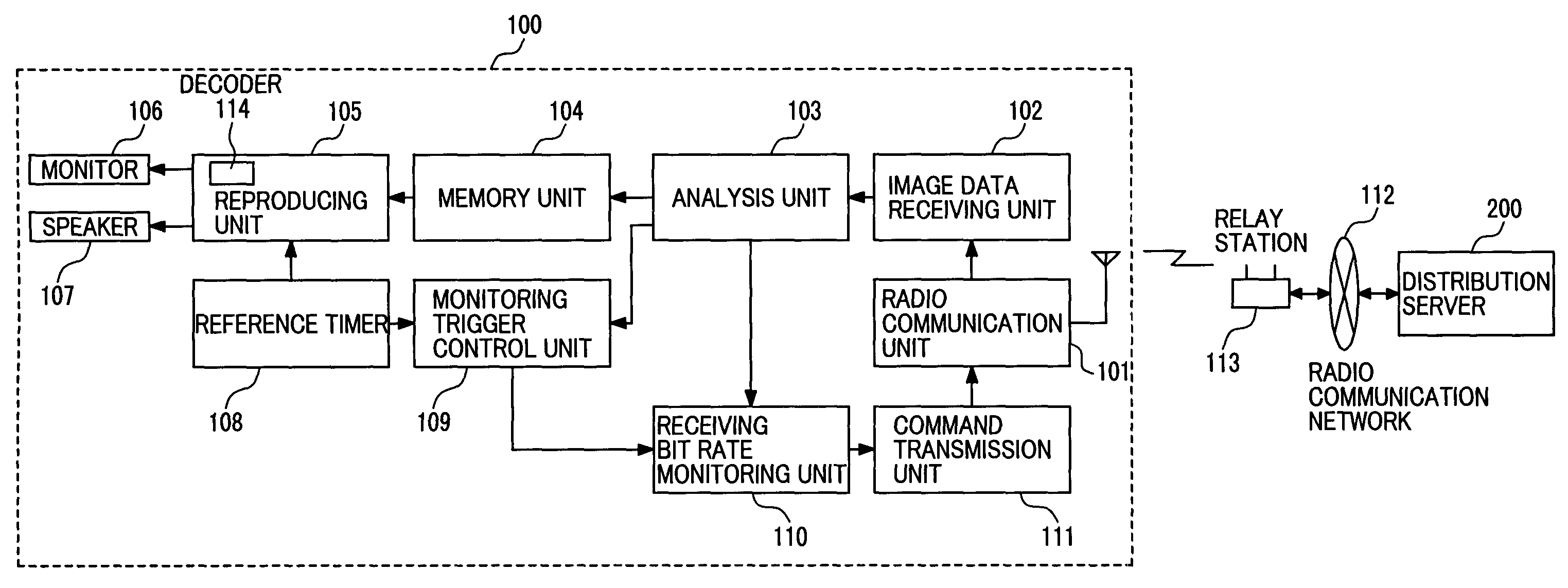
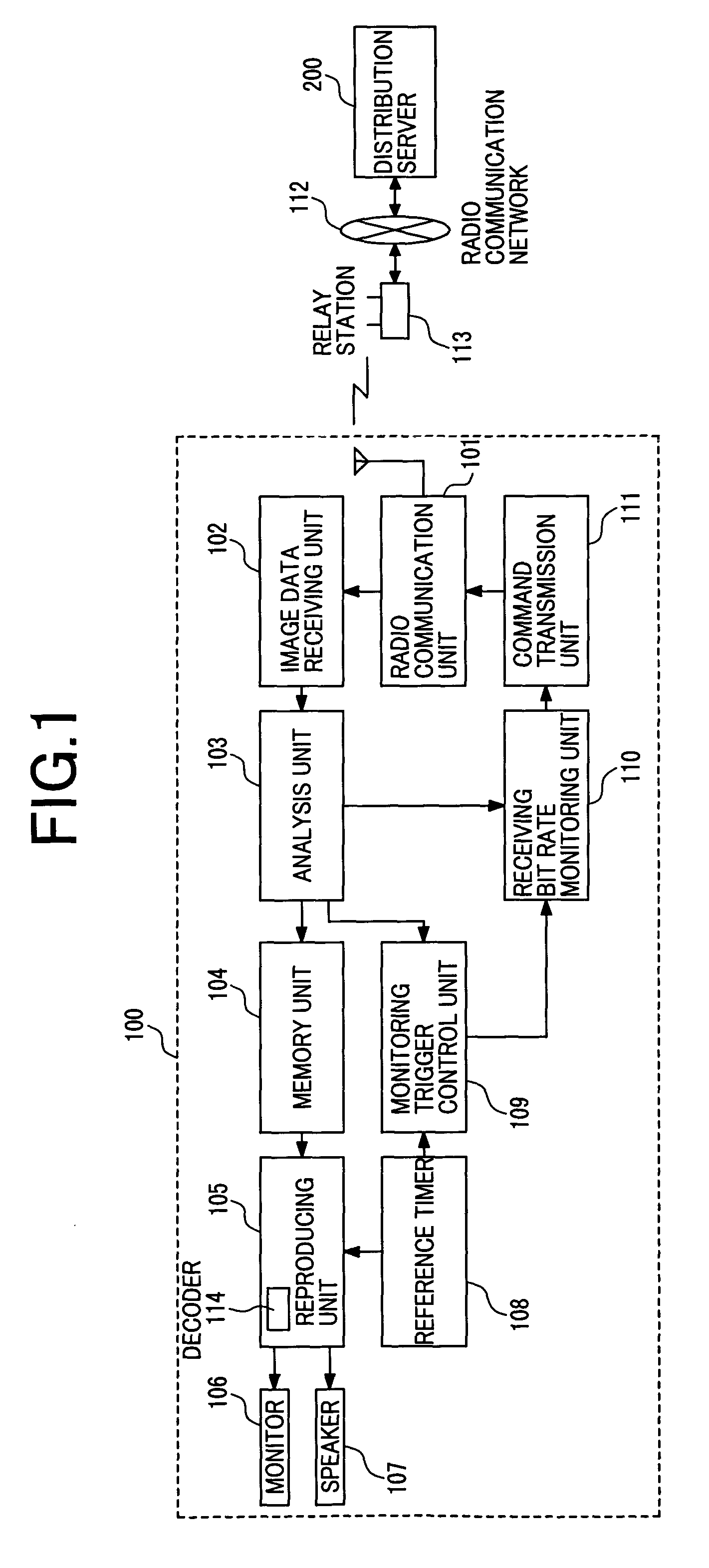
[0037]FIG. 1 shows an example of the configuration of a receiving terminal unit 100 of the present invention.

[0038]Image data received by the receiving terminal unit 100 is data that has been compressed by a predetermined coding system, such as MPEG or the like, and the image data is distributed from a distribution server 200 to the receiving terminal 100 through a radio communication network 112 and a relay station 113.

[0039]The radio communication unit 101 transmits and receives data through radio communication with the distribution server 200. An image data receiving unit 102 receives data transmitted from the distribution server 200. The received image data is stored in a memory unit 104 through an analysis unit 103. The analysis unit 103 performs an extraction to extract monitoring trigger inf...


PUM


Abstract

A radio line is easily influenced in its nature by attenuation or reflection of an electromagnetic wave or the like and the surrounding environment. Due to this fact, a variation of the data transfer speed frequently occurs at the time of image streaming so as to become a hindrance to reproduction of an image at the receiving terminal. A distribution server is provided with a multiplexer for multiplexing information indicating the transmission start time for the image data and a switching unit for switching an image bit rate in response to a request from the receiving terminal. The receiving terminal uses information indicating a transmission start time for the image data, monitors the receiving bit rate and sends out a request for transmission of the most-suitable image bit rate in response to a comparison thereof.

Description

FIELD OF THE INVENTION[0001]This invention relates to an apparatus for switching a bit rate of the distributed image in response to a result of monitoring of a received state of data at a mobile terminal and to a method of switching the bit rate in an image distribution system in which streaming is carried out for the coded image data from the distribution server toward the mobile terminal through a radio circuit.BACKGROUND OF THE INVENTION[0002]In recent years, rapid development of broadband technology and the increased use of a mobile terminal, such as a mobile phone or PDA (Personal Digital Assistance) or the like, have expanded image streaming services under an application of radio infra-structures, such as a cellular phone communication network or radio LAN (Local Area Network) and the like. A problem found in image streaming services under application of a radio network consists in a variation of the electromagnetic wave receiving state. As the receiving state is varied, an er...

Claims


Application Information

Patent Timeline
Patent Type & Authority Patents(United States)
IPC IPC(8): G01R31/08H04B7/26H04M3/42H04M3/487H04M11/00H04N7/173H04N21/2383H04N21/442H04W4/06H04W4/18H04W28/00
CPCH04N7/17318H04N21/234354H04N21/41407H04N21/44209H04N21/4621H04N21/6131H04N21/6373H04N21/8126
Inventor AKIYAMA, YASUHIROKIMURA, JUNICHIYOKOYAMA, TORU
Owner MAXELL HLDG LTD
Why Eureka
Try Eureka