Current mode differential transmission method and system for transmitting three units of data using four signal lines

a transmission method and data technology, applied in the field of current mode differential transmission method and system for differential transmission of three units of data using four signal lines, can solve the problems of distorted waveform of transmitted signals, errors are frequently generated when restoring data, and achieve the effect of reducing the number of signal lines and the number of chip pins

Inactive Publication Date: 2009-03-24
POSTECH ACAD IND FOUND
View PDF6 Cites 26 Cited by
  • Summary
  • Abstract
  • Description
  • Claims
  • Application Information

AI Technical Summary

Benefits of technology

[0008]The present invention provides a current mode differential transmission method for differentially transmitting three units of data using four signal lines, which can be applied to a high speed signal transmission system reducing the number of signal lines and the number of chip pins compared with a conventional differential transmission method and having advantages of the conventional differential transmission method in which common mode noise is removed and a reference voltage is not necessary.
[0009]The present invention also provides a current mode differential transmission system for differentially transmitting three units of data using four signal lines, which can be applied to a high speed signal transmission system reducing the number of signal lines and the number of chip pins compared with a conventional differential transmission method and having advantages of the conventional differential transmission method in which common mode noise is removed and a reference voltage is not necessary.

Problems solved by technology

A single ended transmission method using the reference voltage has two problems when transmitting data at a high data rate.
Accordingly, errors are frequently generated when restoring the data.
Second, a waveform of a transmitted signal is distorted due to switching noise such as ground bounce due to the high data rate transmission.
Since this common mode noise cannot be removed in a receiver, errors are frequently generated when restoring the data.
Accordingly, a unit price of chip increases, and distribution of signal lines is complicated.

Method used


Image

  • Current mode differential transmission method and system for transmitting three units of data using four signal lines
  • Current mode differential transmission method and system for transmitting three units of data using four signal lines
  • Current mode differential transmission method and system for transmitting three units of data using four signal lines

Examples


first embodiment

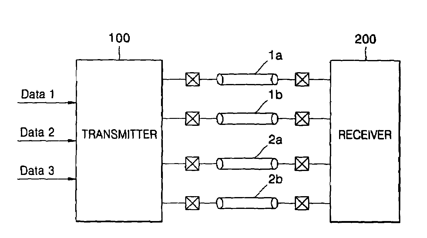
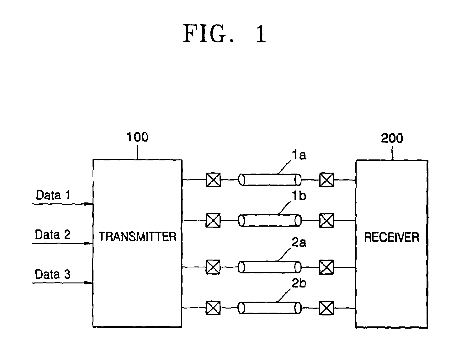
[0031]Referring to FIG. 4A, as the first embodiment, the receiver 200 includes a first comparator 201 for restoring differential data of the first pair of signal lines 1a and 1b, a second comparator 202 for restoring differential data of the second pair of signal lines 2a and 2b, a third comparator 203 for comparing a voltage of the line 1b of the first pair of signal lines 1a and 1b and a voltage of the line 2a of the second pair of signal lines 2a and 2b, a fourth comparator for comparing the voltage of the line 1b of the first pair of signal lines 1a and 1b and a voltage of the line 2b of the second pair of signal lines 2a and 2b, and a multiplexer 207 for obtaining restored third data Data3 by selecting one of the comparison results of the third comparator 203 and the fourth comparator 204 with reference to the first data Data1 and the second data Data2 respectively restored by the first comparator 201 and the second comparator 202.

second embodiment

[0032]Referring to FIG. 4B, as the second embodiment, the receiver 200 includes a first pre-amp 211 and a first comparator 221 for restoring differential data of the first pair of signal lines 1a and 1b, a second pre-amp 212 and a second comparator 222 for restoring differential data of the second pair of signal lines 2a and 2b, and a subtractor 213 and a third comparator for discriminating the third data Data3 by directly comparing the common mode currents of the first pair of signal lines 1a and 1b and the second pair of signal lines 2a and 2b. Referring to FIG. 4C, it is preferable that the subtractor 213 includes a plurality of CMOSs and a plurality of resistors.

[0033]Referring to FIG. 5A, the transmitter 100 includes a plurality of (preferably four) operational amplifiers (OP-Amps). Referring to FIG. 5B, an output driving circuit of the transmitter 100 includes a plurality of CMOSs.

[0034]A current mode differential transmission method realized by the current mode differential t...


PUM


Abstract

Provided are a current mode differential transmission method and system for differentially transmitting three units of data using four signal lines. The method includes: dividing the four signal lines 1a, 1b, 2a and 2b into two pairs of signal lines 1a / 1b and 2a / 2b, and differentially transmitting respective data (first data and second data) via the two pairs of signal lines 1a / 1b and 2a / 2b; and transmitting the other data (third data) by differentially changing common mode currents of the two pairs of signal lines 1a / 1b and 2a / 2b.

Description

BACKGROUND OF THE INVENTION[0001]This application claims the priority of Korean Patent Application No. 10-2004-0055462, filed on Jul. 16, 2004, in the Korean Intellectual Property Office, the disclosure of which is incorporated herein in its entirety by reference.[0002]1. Field of the Invention[0003]The present invention relates to a current mode differential transmission method and system for differentially transmitting three units of data using four signal lines.[0004]2. Description of the Related Art[0005]As well-known to those in the art, a signal transmission system is divided into a single ended transmission system and a differential transmission system. The single ended transmission system transmits a signal using one signal line and a common ground line. In the single ended transmission system, a base power source (for example, 0 voltage) is conducted to the common ground line, and a voltage, i.e., a potential difference, between the one signal line and the common ground lin...

Claims


Application Information

Patent Timeline
Patent Type & Authority Patents(United States)
IPC IPC(8): H04L25/34H04B3/00
CPCH04L5/20H04L25/14H04L25/4923G11C7/00
Inventor CHOI, SEOK WOOPARK, HONG JUNE
Owner POSTECH ACAD IND FOUND
Why Eureka
Try Eureka