Proximity detection using wireless signal strengths

a wireless signal and strength technology, applied in the field of computer systems and networks, can solve the problems of only finding other properly-enabled computing devices, unable to measure (x,y) locations, and unable to find other resources

Inactive Publication Date: 2009-03-24
MICROSOFT TECH LICENSING LLC
View PDF17 Cites 233 Cited by
  • Summary
  • Abstract
  • Description
  • Claims
  • Application Information

AI Technical Summary

Benefits of technology

[0016]The proximity detection of the present invention is also useful in detecting synchronous user operations between mobile devices for co-located collaboration, such as for stitching, which refers to sharing the screen coordinates, direction, and timing of pen strokes with other nearby devices to establish when a pen stroke spans the displays of two devices. The proximity detection of the present invention solves the problem of determining which devices to consider as candidates for potential synchronous user operations, since any device not within short range proximity is eliminated as a candidate.

Problems solved by technology

However, measuring (x,y) locations is difficult, because it requires extensive setup and calibration; the problem is especially difficult indoors where many people spend most of their time, and where GPS does not work.
However, drawbacks to these mechanisms include that users have to be on the same network in order to find each other, and that only other people can be found, as opposed to other things.
There are well-established protocols for peer-to-peer device discovery using Bluetooth and Infrared Data Association (IrDA), however the discovery range of Bluetooth is limited to about 10 meters, and IrDA requires a clear line of sight between devices, and only works over a range of about one meter.
Further, these mechanisms only find other properly-enabled computing devices, not other resources such as the nearest elevator, bathroom, or vending machine.

Method used


Image

  • Proximity detection using wireless signal strengths
  • Proximity detection using wireless signal strengths
  • Proximity detection using wireless signal strengths

Examples


Embodiment Construction

Exemplary Operating Environment

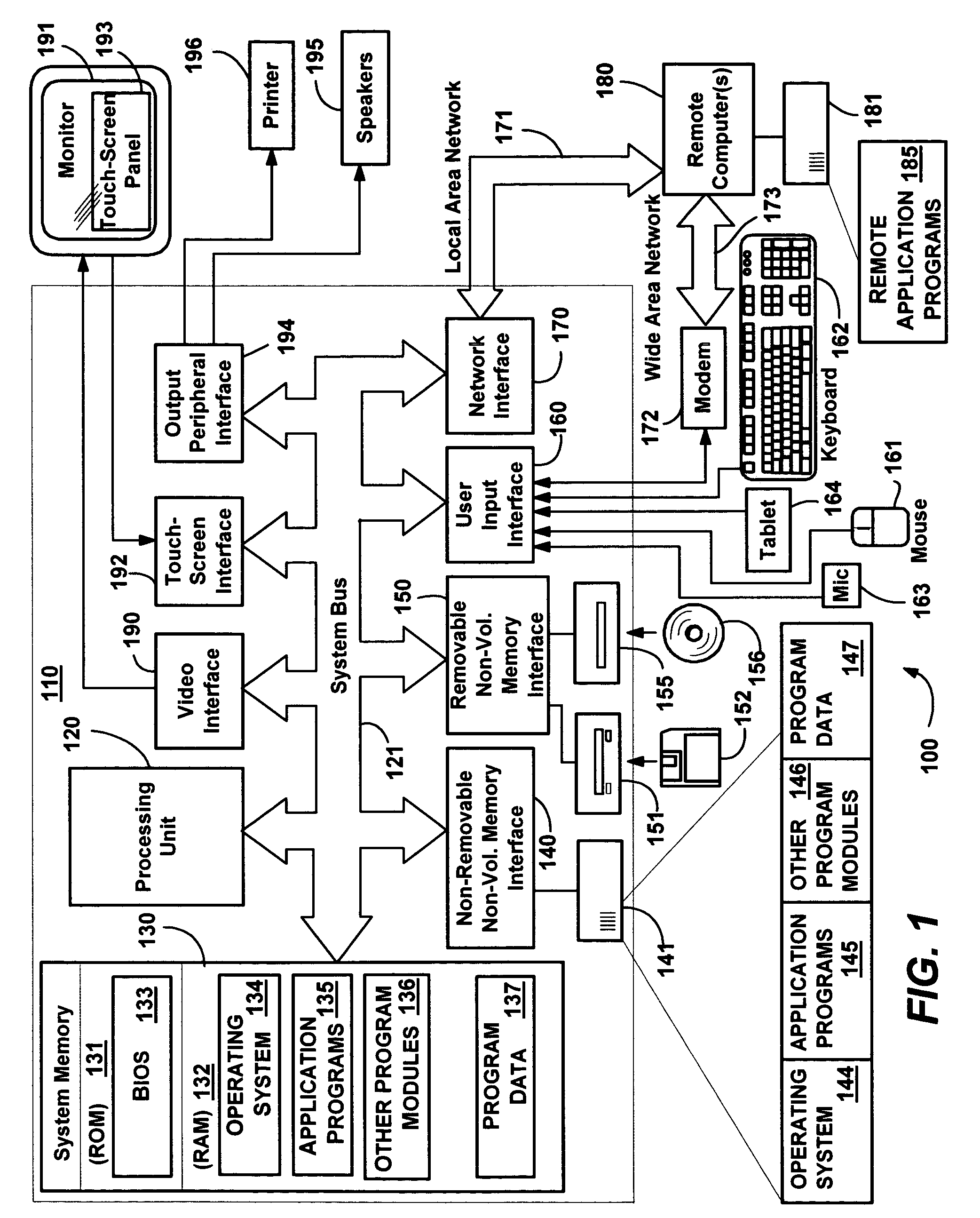
[0025]FIG. 1 illustrates an example of a suitable computing system environment 100 on which the invention may be implemented. The computing system environment 100 is only one example of a suitable computing environment and is not intended to suggest any limitation as to the scope of use or functionality of the invention. Neither should the computing environment 100 be interpreted as having any dependency or requirement relating to any one or combination of components illustrated in the exemplary operating environment 100.

[0026]The invention is operational with numerous other general purpose or special purpose computing system environments or configurations. Examples of well known computing systems, environments, and / or configurations that may be suitable for use with the invention include, but are not limited to, personal computers, server computers, hand-held or laptop devices, tablet devices, multiprocessor systems, microprocessor-based systems, set ...


PUM


Abstract

Described is a system and method in a wireless (Wi-Fi) network comprising a server, clients and various mechanisms that compute lists of other clients and resources that are physically nearby. Clients report Wi-Fi access points' signal strengths to a server, which uses that data to compute the proximity of resources to one another, including an estimate the distance between resources. The data may be returned to the client as a list of resources within short range proximity, or resources within long-range proximity, with an approximate time to that resource based on previous clients' reporting. Because proximity is used rather than absolute location, only minimal setup is needed. As the number of clients and resources that use the system increases, the server knowledge also increases with respect to the number of resources that can be found and in the physical range over which other people and places can be found.

Description

FIELD OF THE INVENTION[0001]The invention relates generally to computer systems and networks, and more particularly to computer systems employing wireless communications.BACKGROUND OF THE INVENTION[0002]One of the goals of ubiquitous computing is to build applications that are sensitive to the computer user's context. One important aspect of context includes the people and places that are close to the user. For example, at conferences, meetings and other social engagements, people interact with one another fairly regularly, and often see the same people at many such events. Various mechanisms have been tried to help people remember and / or discover the identities of others.[0003]These mechanisms are based on location sensing and / or proximity sensing. Location sensing determines the absolute position (e.g., x,y coordinates) of a person, whereas proximity sensing discovers other people around a given user. Note that one common way to determine proximity is to measure absolute locations...

Claims


Application Information

Patent Timeline
Patent Type & Authority Patents(United States)
IPC IPC(8): H04W24/00H04W64/00G01S19/13
CPCH04N21/4126H04W64/00H04W24/00G06F15/16
Inventor KRUMM, JOHN C.HINCKLEY, KENNETH P.
Owner MICROSOFT TECH LICENSING LLC
Why Eureka
Try Eureka